Solar cell module and method of manufacturing the same
Active Publication Date: 2010-01-28
PANASONIC INTELLECTUAL PROPERTY MANAGEMENT CO LTD
View PDF1 Cites 9 Cited by
- Summary
- Abstract
- Description
- Claims
- Application Information
AI Technical Summary
Benefits of technology
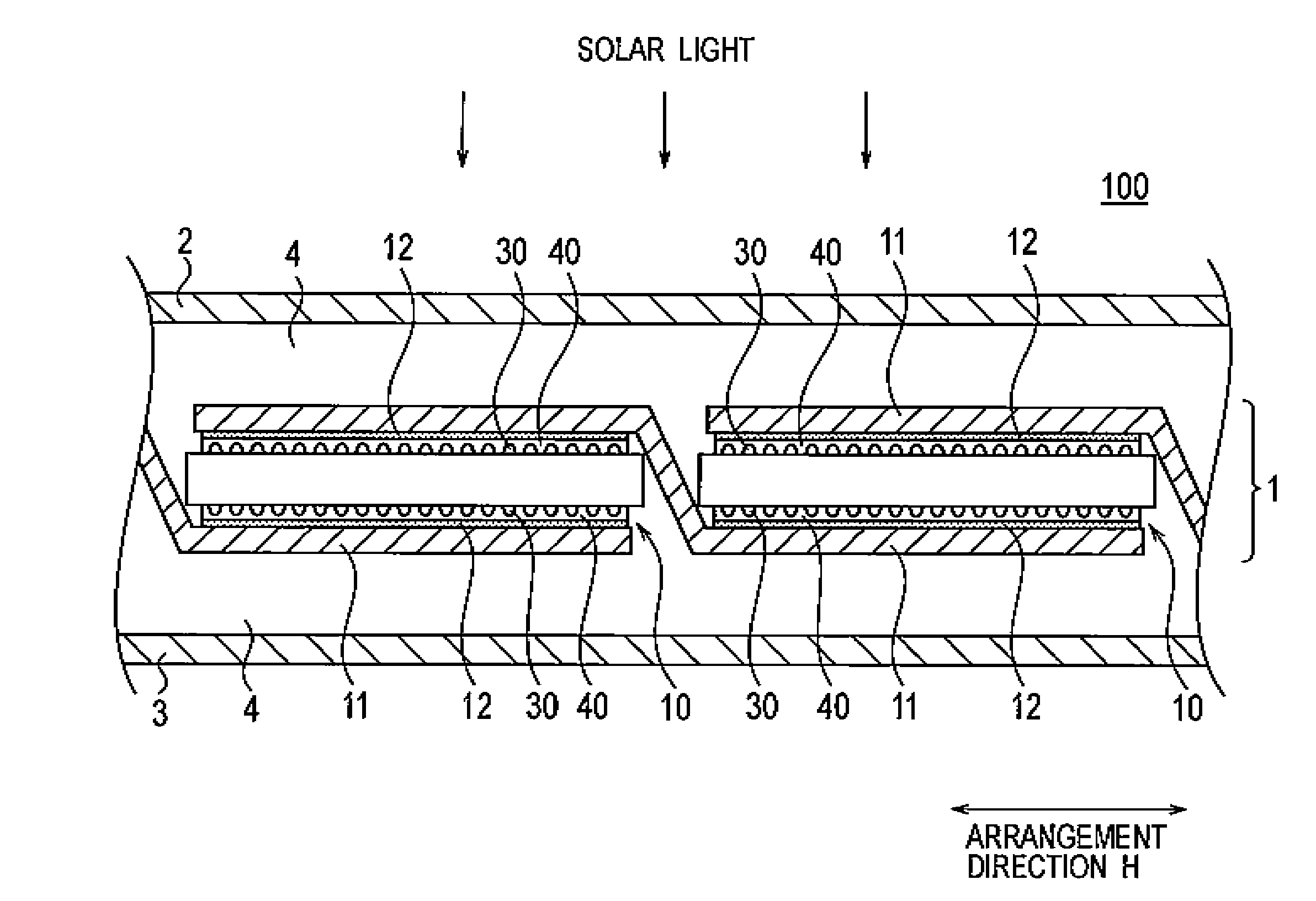
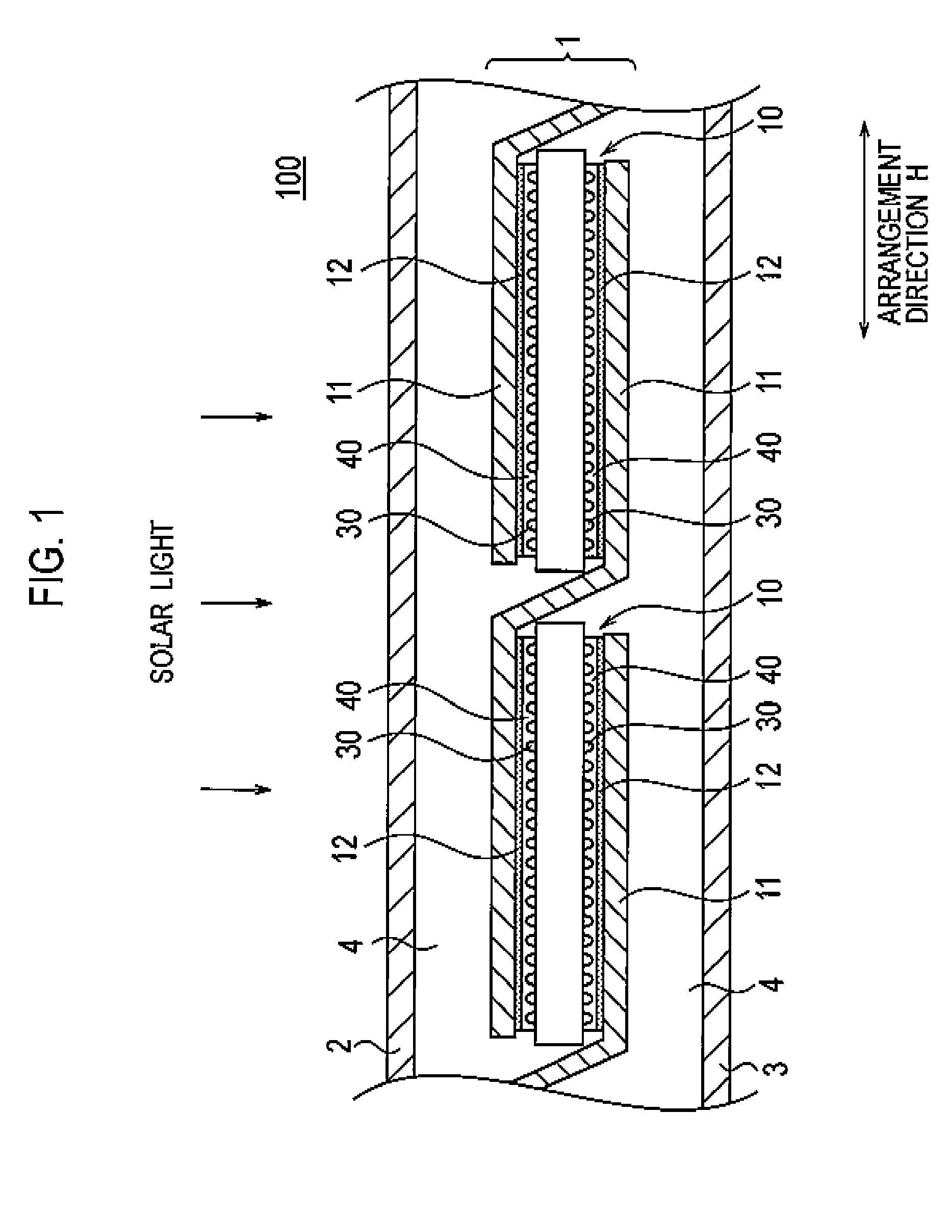
[0074]In the solar cell module 100 according to this embodiment, the resin adhesive 12 includes the plurality of removed portions 12a formed by removing the resin material 12 in the direction vertical to the main surface of the photoelectric conversion part 20. The removed portions 12a lie in a row in directions (the cross directions K) crossing the arrangement directions H.
[0075]As described above, the resin adhesive 12 includes the plurality of removed portions 12a lain in the row in directions (the cross direction K) crossing the arrangement directions H. Thus, the macromolecules constituting the resin adhesive 12 are divided by the plurality of removed portions 12a in the arrangement directions H. With this configuration, stress in the arrangement directions H remaining inside the resin adhesive 12 can be reduced. As a result, microscopic exfoliation in an interface between the resin adhesive 12 and the wiring member 11 or an interface between the resin adhesive 12 and the connection electrode 40, or a microscopic crack inside the resin adhesive 12, which is likely to occur over time, can be prevented.
[0076]In the method of manufacturing the solar cell module 100 according to this embodiment, the wiring members 11 and the solar cell 10 are mutually pressed. Thereby, the plurality of the convex parts are caused to dent in the conductive layer in the wiring member 11, and the plurality of removed portions 12a are consequently formed. In ad
Problems solved by technology
Such stress may cause, over time, microscopic exfoliation in an interface between a resin adhesive and an wiring membe
Method used
View moreImage
Smart ImageViewing Examples

Examples
 PUM
 Abstract
In the solar cell module 100, the resin adhesive 12 includes a plurality of removed portions 12a on the principal surface of the photoelectric conversion part 20 by removing the resin adhesive 12 in a vertical direction. The plurality of removed portions 12a are formed in the row in cross directions K.
Description
CROSS REFERENCE TO RELATED APPLICATIONS[0001]This application is based upon and claims the benefit of priority from prior Japanese Patent Application No. 2007-338138, filed on Dec. 27, 2007; the entire contents of which are incorporated herein by reference.BACKGROUND OF THE INVENTION[0002]1. Field of the Invention[0003]The present invention relates to a solar cell module including wiring members, and a method of manufacturing such a solar cell module.[0004]2. Description of the Related Art[0005]Expectation has been placed on solar cells as a new energy source because solar cells can convert clean, inexhaustibly supplied solar light directly into electricity.[0006]Generally, a solar cell outputs electrical power of only several watts. For this reason, when a solar cell is used as a power supply for a house or a building, a solar cell module with the output power enhanced by electrically connecting a plurality of solar cells. The plurality of solar cells are arranged in arrangement di...
Claims
Login to View More Application Information
Patent Timeline
 IPC IPC(8): H01L31/042H01L21/28
CPCH01L31/0747H01L31/0512Y02E10/50H01L31/042
Inventor YOSHIMINE, YUKIHIROKANNO, HIROSHIHASHIMOTO, HARUHISASAITA, ATSUSHITAIRA, SHIGEHARU
Owner PANASONIC INTELLECTUAL PROPERTY MANAGEMENT CO LTD
Features
- R&D
- Intellectual Property
- Life Sciences
- Materials
- Tech Scout
- Unparalleled Data Quality
- Higher Quality Content
- 60% Fewer Hallucinations
Learn More Browse by: Latest US Patents, China's latest patents, Technical Efficacy Thesaurus, Application Domain, Technology Topic, Popular Technical Reports.
© 2025 PatSnap. All rights reserved.Legal|Privacy policy|Modern Slavery Act Transparency Statement|Sitemap|About US| Contact US: help@patsnap.com