Light guide plate and illuminated keyboard

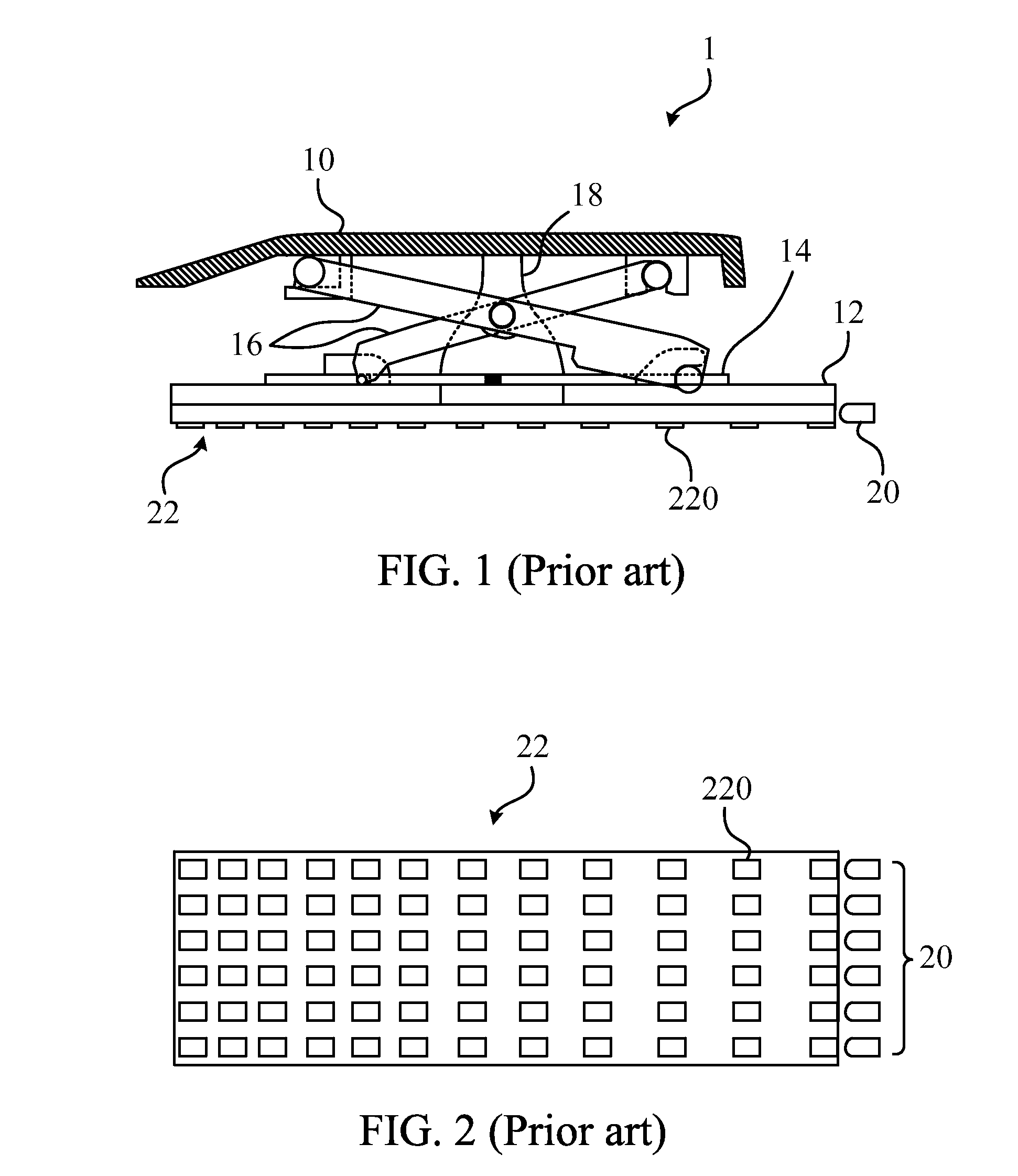
a technology of illuminated keyboards and guide plates, which is applied in the direction of contact mechanisms, lighting and heating apparatuses, instruments, etc., can solve the problems of poor luminance effect reflected by white ink b>220/b>, the condition of touching wrong keys will usually happen, and the visual effect of the user using the illuminated keyboard will be affected. , to achieve the effect of enhancing the luminance

Inactive Publication Date: 2010-01-28
DARFON ELECTRONICS CORP
View PDF3 Cites 4 Cited by
  • Summary
  • Abstract
  • Description
  • Claims
  • Application Information

AI Technical Summary

Benefits of technology

[0010]A scope of the invention is to provide a light guide plate to enhance the luminance effect by changing the color of the printed ink.
[0011]According to an embodiment of the invention, the light guide plate cooperates with a light source to effectively reflect the lights emitted from the light source, so that the luminance effect will be greatly enhanced. The light guide plate includes a main body and a reflective portion. The light source is disposed near the main body of the light guide plate, and the reflective portion is printed on a bottom of the main body.
[0013]In practical applications, if the light source is a non-white light source, an ink having a color the same with the non-white light source is printed on the bottom of the main body to be the above-mentioned reflective portion. By doing so, no matter what color the light emitted from the non-white light source is, the light will be reflected by the ink with the same color to enhance the luminance effect.

Problems solved by technology

If the user is in a light-insufficient environment, the conditions of touching wrong keys will usually happen.
However, since the white ink 220 is printed in the conventional light guide plate 22, if the light emitted from the light source 20 is not the white light (e.g., a blue light, a red light, and so on), the luminance effect reflected by the white ink 220 will become poor, and the visual effect when the user uses the illuminated keyboard will be also affected.
Moreover, if the user wants that some keyswitch modules of the illuminated keyboard show different colors, the light source 20 capable of emitting lights of different colors is needed, and the manufacturing cost will be increased accordingly.

Method used


Image

  • Light guide plate and illuminated keyboard
  • Light guide plate and illuminated keyboard
  • Light guide plate and illuminated keyboard

Examples


Embodiment Construction

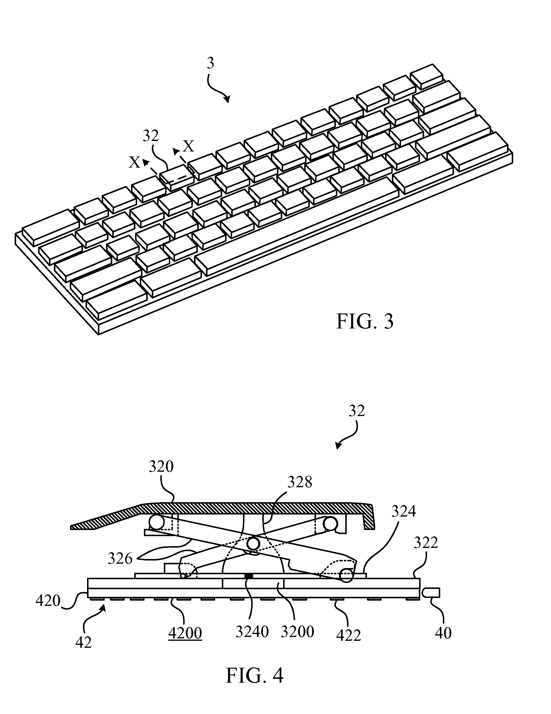
[0025]Please refer to FIG. 3. FIG. 3 shows a scheme diagram of the illuminated keyboard 3 in an embodiment according to the invention. As shown in FIG. 3, the illuminated keyboard 3 includes a plurality of keyswitch modules 32. The keyswitch module 32 is used for the user to press to perform the function the user wants to input.

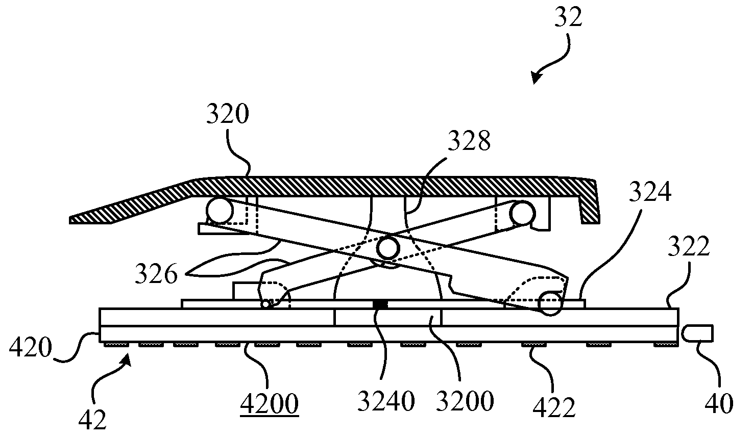
[0026]Please refer to FIG. 4 and FIG. 5. FIG. 4 shows a cross-sectional view of the keyswitch module 32 along the X-X line in FIG. 3. FIG. 5 shows an exploded view of the keyswitch module 32 in FIG. 4. In this embodiment, the keyswitch module 32 includes a keycap 320, a substrate 322, a circuit board 324, a supporting device 326, and an elastic component 328. The supporting device 326 and the elastic component 328 are both disposed between the keycap 320 and the substrate 322, wherein the supporting device 326 can make the keycap 320 capable of moving upward and downward relative to the substrate 322, and the elastic component 328 is used for supporting the k...


PUM


Abstract

The invention discloses a light guide plate applied to an illuminated keyboard. A plurality of keyswitch modules is installed on the illuminated keyboard. The light guide plate is disposed beneath the keyswitch modules. The light guide plate comprises a main body and a reflective portion printed on a bottom of the main body. A light source is disposed close to the main body of the light guide plate. If the light source emits white light, the color of the reflective portion is different from that of the light source. If the light source emits non-white light, the color of the reflective portion is the same as that of the light source. Accordingly, the luminance will be greatly enhanced.

Description

BACKGROUND OF THE INVENTION[0001]1. Field of the Invention[0002]The invention relates to a light guide plate, and more particularly, to a light guide plate enhancing the luminance effect by changing the color of the printed ink and an illuminated keyboard using the light guide plate.[0003]2. Description of the Prior Art[0004]When a user uses a personal computer, a keyboard is one of the necessary inputting devices used for inputting words, symbols, or numbers. Additionally, the keyswitch structure is set on the consumer electronic products used in our daily life or the large-sized manufacturing apparatus used in industry as the inputting apparatus to operate the above-mentioned electronic products or manufacturing apparatus.[0005]Please refer to FIG. 1. FIG. 1 shows a cross-sectional view of a keyswitch module 1 in the prior art. As shown in FIG. 1, the conventional keyswitch module 1 includes a keycap 10, a substrate 12, a circuit board 14, a supporting device 16 and an elastic com...

Claims


Application Information

Patent Timeline
Patent Type & Authority Applications(United States)
IPC IPC(8): H01H9/00F21V7/00
CPCG02B6/0055G02B6/006G02B6/0061H01H2219/062H01H3/122H01H2219/044G02B6/0073
Inventor LIN, CHIN HUNG
Owner DARFON ELECTRONICS CORP
Why Eureka
Try Eureka