
Engine valve assembly with valve can mountable to an engine cover

a technology of engine valves and components, which is applied in the direction of valve housings, non-mechanical valves, magnetic bodies, etc., can solve the problems of difficult access to the fastener opening closer to the engine cover surface, and achieve the effect of convenient fit in the available packaging spa

Inactive Publication Date: 2010-01-28
EATON CORP
View PDF17 Cites 28 Cited by
  • Summary
  • Abstract
  • Description
  • Claims
  • Application Information

AI Technical Summary

Benefits of technology

[0004]An engine valve assembly is provided with a valve housing, also referred to as a can or cover, that is configured to promote easy access to a fastener used for fastening and removing the valve assembly from an engine cover. The valve assembly may be a solenoid-type oil control valve assembly or other type of engine valve that mounts to an engine cover, and the engine cover may be a cam cover, or any portion of an engine block. The can has a first wall and a side wall that extends therefrom to partially define an interior cavity with a cavity opening opposite the first wall. In some embodiments, the first wall has a generally teardrop-shaped surface, as described in detail herein. The first wall has a valve opening as well as a fastener opening that is spaced from and aligned with the valve opening along the first wall. A valve body is supported by the valve housing at least partially within the interior cavity, and may be press-fit therein, in alignment with the valve opening. The valve housing is configured to mount to the engine cover with the fastener inserted through the fastener opening to extend through the interior cavity and fasten to the engine cover, with the valve body extending into the engine cover. Separation of the fastener opening from the face of the engine cover by the side wall makes the fastener more accessible for insertion and removal, especially if the engine cover has unusual surface geometry or adjacent components that would make access to a fastener opening closer to the engine cover surface more difficult. Cans that have a teardrop-shaped surface may more easily fit in available packaging space on the engine cover due to the tapered nature of the teardrop shape.

Problems solved by technology

Separation of the fastener opening from the face of the engine cover by the side wall makes the fastener more accessible for insertion and removal, especially if the engine cover has unusual surface geometry or adjacent components that would make access to a fastener opening closer to the engine cover surface more difficult.

Method used


Image

  • Engine valve assembly with valve can mountable to an engine cover
  • Engine valve assembly with valve can mountable to an engine cover
  • Engine valve assembly with valve can mountable to an engine cover

Examples


Embodiment Construction

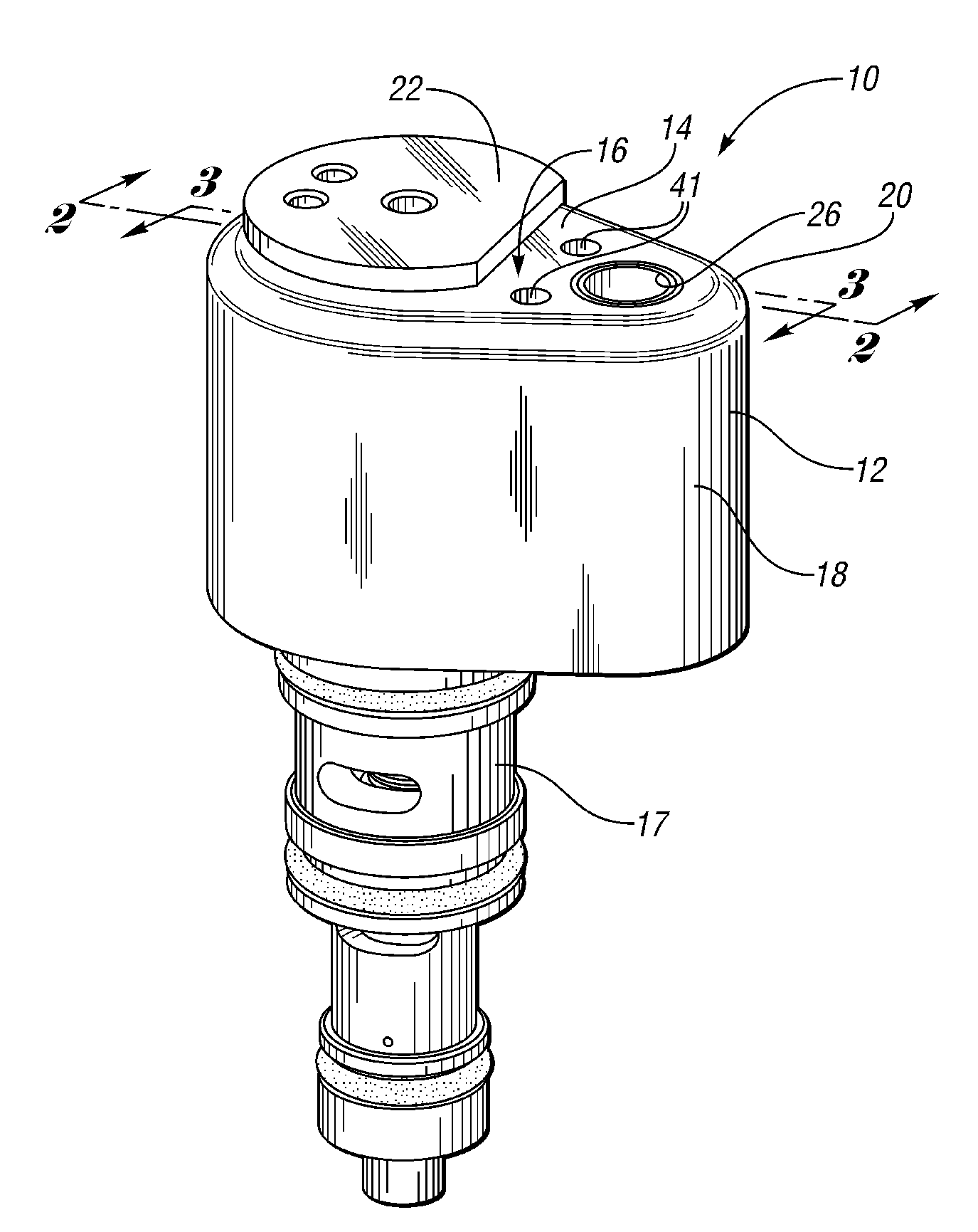
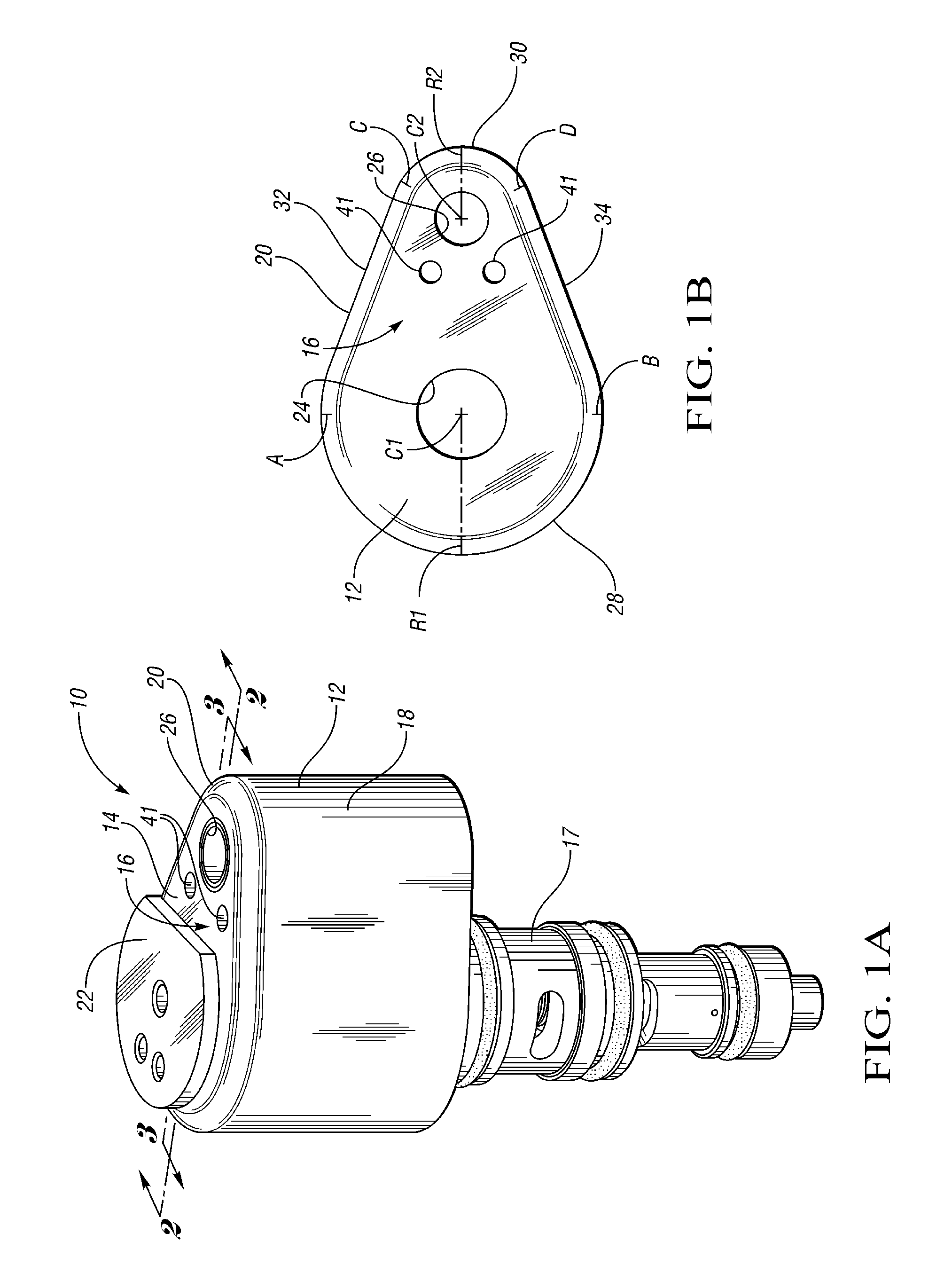
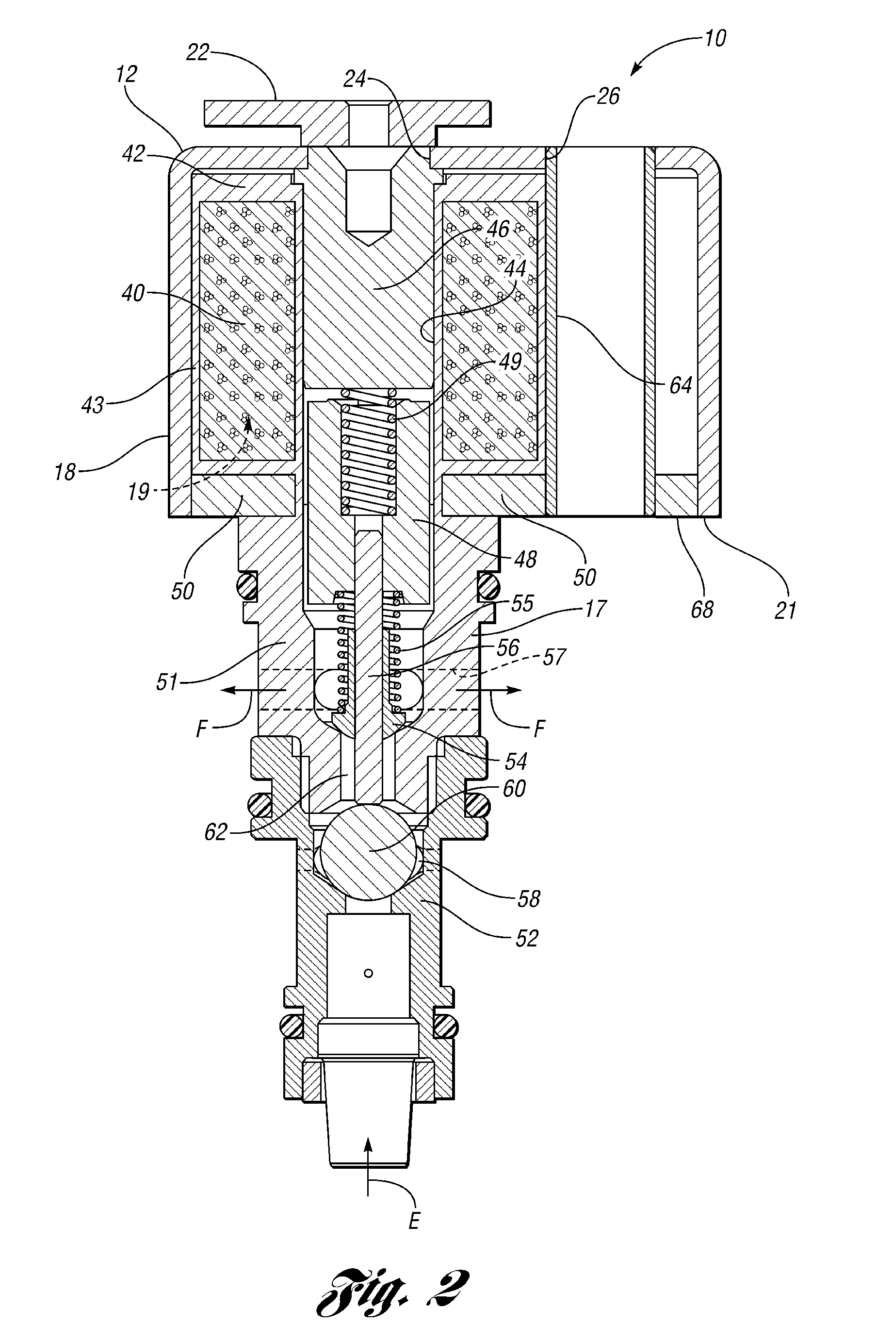
[0018]Referring to the drawings, wherein like reference numbers refer to like components, FIG. 1A shows an engine oil control valve assembly 10 including a valve housing 12, also referred to as a can or cap, with a first wall 14 having a generally teardrop-shaped face 16. A valve body 17 extends from the can 12. The valve can 12 includes a side wall 18 extending from a periphery 20 of the first wall 14, generally perpendicularly to the face 16. The valve body 17 is press-fit into an interior cavity 19 formed by the face 16 and side wall 18 (shown in FIG. 2), through a cavity opening at terminal end 21 of the side wall 18. The periphery 20 is shown most clearly in FIG. 1B. A pole piece cover 22 shown in FIG. 1A is removed in FIG. 1B to reveal a valve opening 24 in the first wall 14. A fastener opening 26 is displaced laterally from the valve opening 24 along the face 16.

[0019]Referring to FIG. 1B, the teardrop-shaped face 16 is determined by the periphery 20, which has a first portio...


PUM


Abstract

An engine valve assembly is provided with a valve housing configured to promote easy fastening and removal of the valve assembly from an engine cover. The housing has a first wall and a side wall that extends therefrom to partially define an interior cavity with a cavity opening opposite the first wall. In some embodiments, the first wall has a generally teardrop-shaped surface. The first wall has a valve opening and a fastener opening that is spaced from and aligned with the valve opening along the first wall. A valve body is supported by the valve housing at least partially within the interior cavity, and may be press-fit therein. The valve housing mounts to the engine cover with the fastener inserted through the fastener opening to extend through the interior cavity and fasten to the engine cover, with the valve body extending into the engine cover.

Description

CROSS-REFERENCE TO RELATED APPLICATIONS[0001]This application claims the benefit of U.S. Provisional Application 61 / 083,663, filed Jul. 25, 2008, which is hereby incorporated by reference in its entirety.TECHNICAL FIELD[0002]The invention relates to an engine valve assembly mountable to an engine cover.BACKGROUND OF THE INVENTION[0003]An electro-hydraulic system of valves typically controls inlet and exhaust from engine cylinders, as well as the amount of valve lift, in a modern automotive engine. Multiple valves are typically mounted to an engine cam cover. The cover is often of complex topography and must accommodate a variety of other components. An electro-hydraulic valve for an engine that fastens to the cam cover without interference from other components and in an ergonomic manner is desired.SUMMARY OF THE INVENTION[0004]An engine valve assembly is provided with a valve housing, also referred to as a can or cover, that is configured to promote easy access to a fastener used f...

Claims


Application Information

Patent Timeline
Patent Type & Authority Applications(United States)
IPC IPC(8): F16K27/00F01L9/10F01L9/11
CPCF01L9/02F01L13/0005F01L2001/34426F01L2001/3443F16K27/029F16K27/0245F16K31/0637H01F7/1607F01L2001/34433F01L9/10F16K31/06F01L13/00F01M1/16
Inventor KELLER, ROBERT D.BOYCHUK, ROBERT J.
Owner EATON CORP
Learn More