Muffler for an exhaust system

a technology of exhaust system and muffler, which is applied in the direction of mechanical equipment, machines/engines, pipe elements, etc., can solve the problems of requiring close manufacturing tolerances and stuck intermediate bottoms b>122/b>, and achieve the effect of improving mounting, reducing production costs and muffler weigh

Inactive Publication Date: 2010-01-28
EMCON TECHNOLOGIES GERMANY (AUGSBURG) GMBH
View PDF18 Cites 1 Cited by
  • Summary
  • Abstract
  • Description
  • Claims
  • Application Information

AI Technical Summary

Benefits of technology

[0005]According to one example of the invention, in a muffler of the type initially mentioned, improved mounting is achieved by a common intermediate bottom that holds the pipe ends on the housing. In particular, the intermediate bottom extends perpendicularly to a longitudinal axis of the housing and of the inlet and outlet pipes, respectively. In comparison with the prior art, the con

Problems solved by technology

One disadvantage with this known configuration is that if there are temperature-related extensions of the inlet and outlet pipes 114, 116, the inte

Method used


Image

  • Muffler for an exhaust system
  • Muffler for an exhaust system
  • Muffler for an exhaust system

Examples


Embodiment Construction

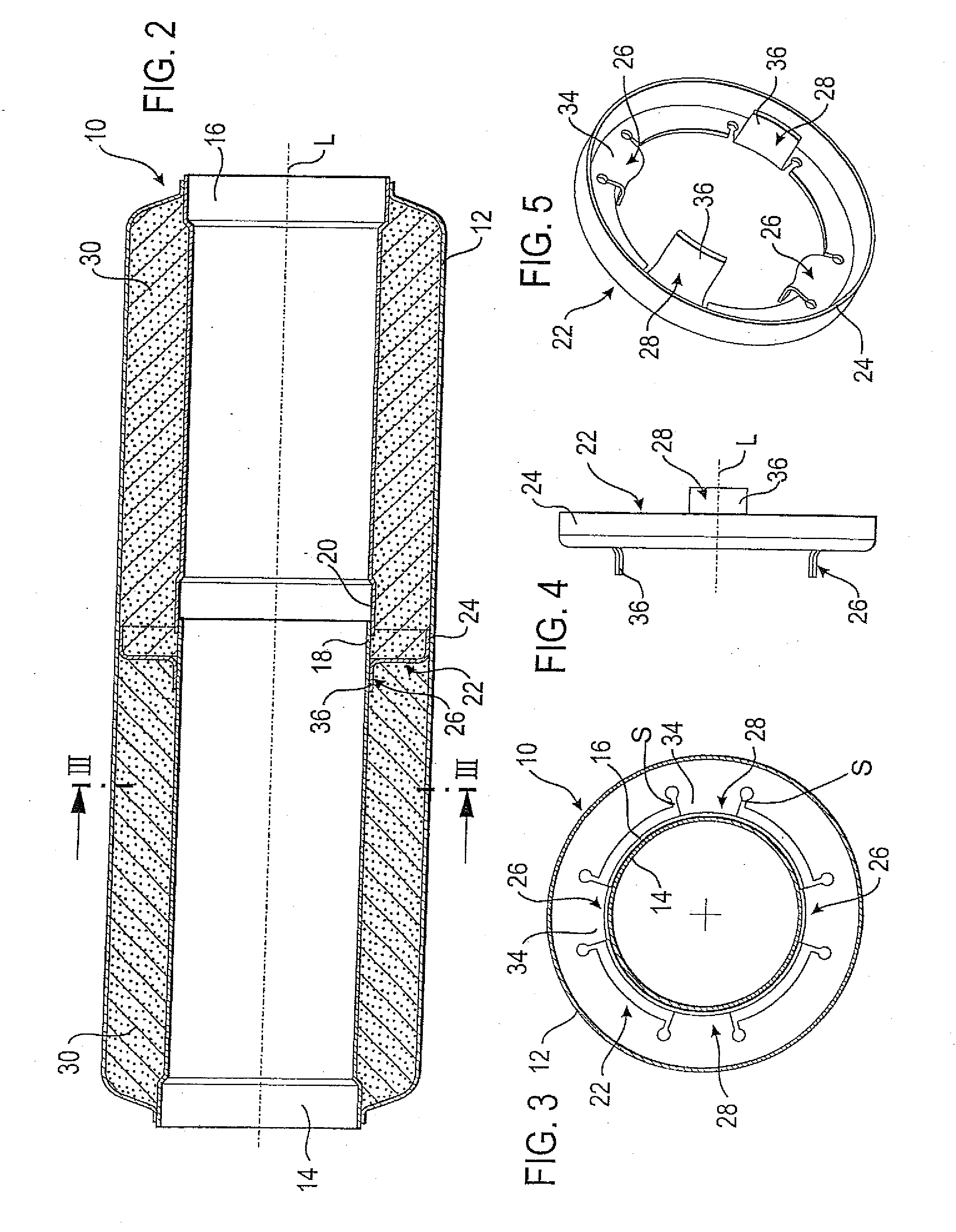
[0027]FIGS. 2 and 3 show a muffler 10 according to one example of the invention for an exhaust system of a combustion engine, in the present case of a motor vehicle. The muffler 10 has a housing 12, and an inlet pipe 14 and an outlet pipe 16 that are arranged in the housing. The inlet and outlet sides may of course be exchanged. Both the inlet pipe 14 and the outlet pipe 16 have a pipe end 18 and 20, respectively, arranged inside the housing 12, with the pipe end 18 being inserted into the slightly expanded pipe end 20 in the example shown

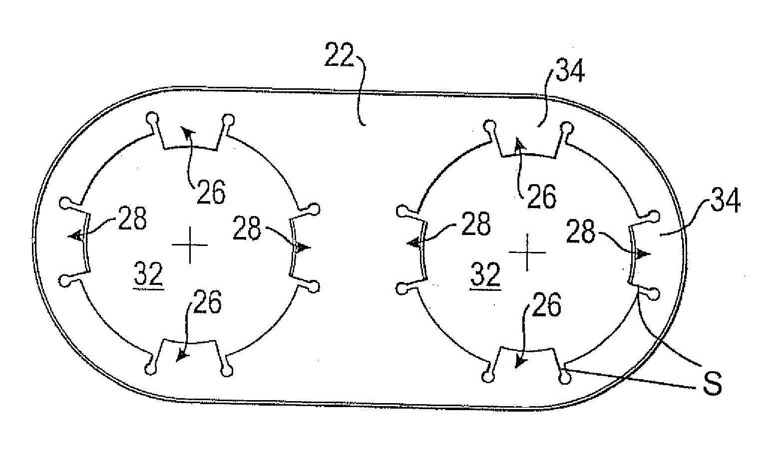
[0028]For holding the two pipe ends 18, 20, a common annular intermediate bottom 22 is provided which is illustrated separately in FIGS. 4 and 5. The intermediate bottom 22 is for example configured as a stamped sheet metal part and has an encircling reshaped rim 24 that allows the intermediate bottom 22 to rest against the housing 12. In the embodiment shown, the intermediate bottom 22 is firmly connected with the housing 12 in the region of the r...


PUM


Abstract

A muffler for an exhaust system of a combustion engine has a housing and at least one inlet pipe and at least one outlet pipe each having a pipe end arranged inside the housing. A common intermediate bottom is provided for holding the pipe ends on the housing.

Description

RELATED APPLICATIONS[0001]The application is the U.S. National Phase of PCT / EP2007 / 003005 filed Apr. 3, 2007, which claimed priority to German Application 10 2006 017 812.2 filed Apr. 13, 2006.TECHNICAL FIELD[0002]The invention relates to a muffler for an exhaust system of a combustion engine, in particular of a motor vehicle, having a housing and at least one inlet pipe and at least one outlet pipe each having a pipe end arranged inside the housing. Such mufflers are mounted in motor vehicles, aircrafts and watercrafts.BACKGROUND OF THE INVENTION[0003]FIG. 1 shows such a simple muffler 110 according to the prior art. The muffler 110 has a housing 112, an inlet pipe 114 and an outlet pipe 116. A respective annular intermediate bottom 122 is provided for holding free pipe ends 118 and 120, respectively. The annular intermediate bottom 122 is fastened to the respective pipe end 118 or 120 and has a push fit with respect to the housing 112. One disadvantage with this known configuratio...

Claims


Application Information

Patent Timeline
IPC IPC(8): F16L39/00F01N13/18F01N13/08
CPCF01N1/02F01N2490/155F01N13/18F01N3/0842F01N3/208Y02T10/12
Inventor TREFZGER, ERIK
Owner EMCON TECHNOLOGIES GERMANY (AUGSBURG) GMBH
Why Eureka
Try Eureka