Multiple switch node power converter control scheme that avoids switching sub-harmonics

a control scheme and switch node technology, applied in power conversion systems, dc-dc conversion, pulse techniques, etc., can solve the problems of buck-boost mode, buck-boost mode, buck-boost mode, etc., to eliminate any sub-harmonic switching and generate surplus energy

Active Publication Date: 2010-01-28
TEXAS INSTR INC
View PDF4 Cites 27 Cited by
  • Summary
  • Abstract
  • Description
  • Claims
  • Application Information

AI Technical Summary

Benefits of technology

[0030]The introduction of fixed-width or fixed duty cycle pulses to complementary switching pair S3 and S4 generates surplus energy because the duty cycle or pulse-width of complementary switching pair S3 and S4 is now greater than its required value. However, since the voltage error signal is still continuously modulated by the buck modulation ramp, the pulse width modulation feedback loop can compensate for the energy discrepancy, e.g., by decreasing the pulse-width or duty cycle of the buck pulse. The net effect is that the power converter reaches its optimal operating point without overlap and eliminates any subharmonic switching.

Problems solved by technology

In practice, however, the ideal case rarely occurs.
As a result, maximum and minimum duty cycles or pulse widths for the buck and boost modes never reach their ideal limits.
Instead and as a result, a transitional, buck-boost mode occurs, which can be problematic.
The minimum boost mode duty cycle is also limited.
Problematically, with subharmonic switching, the voltage error signal oscillates.
Although not shown, the inductor current shows similar ripple effects, raising EMI concerns.
As a result, higher current / voltage ripple and increased power loss can ensue.

Method used


Image

  • Multiple switch node power converter control scheme that avoids switching sub-harmonics
  • Multiple switch node power converter control scheme that avoids switching sub-harmonics
  • Multiple switch node power converter control scheme that avoids switching sub-harmonics

Examples


Embodiment Construction

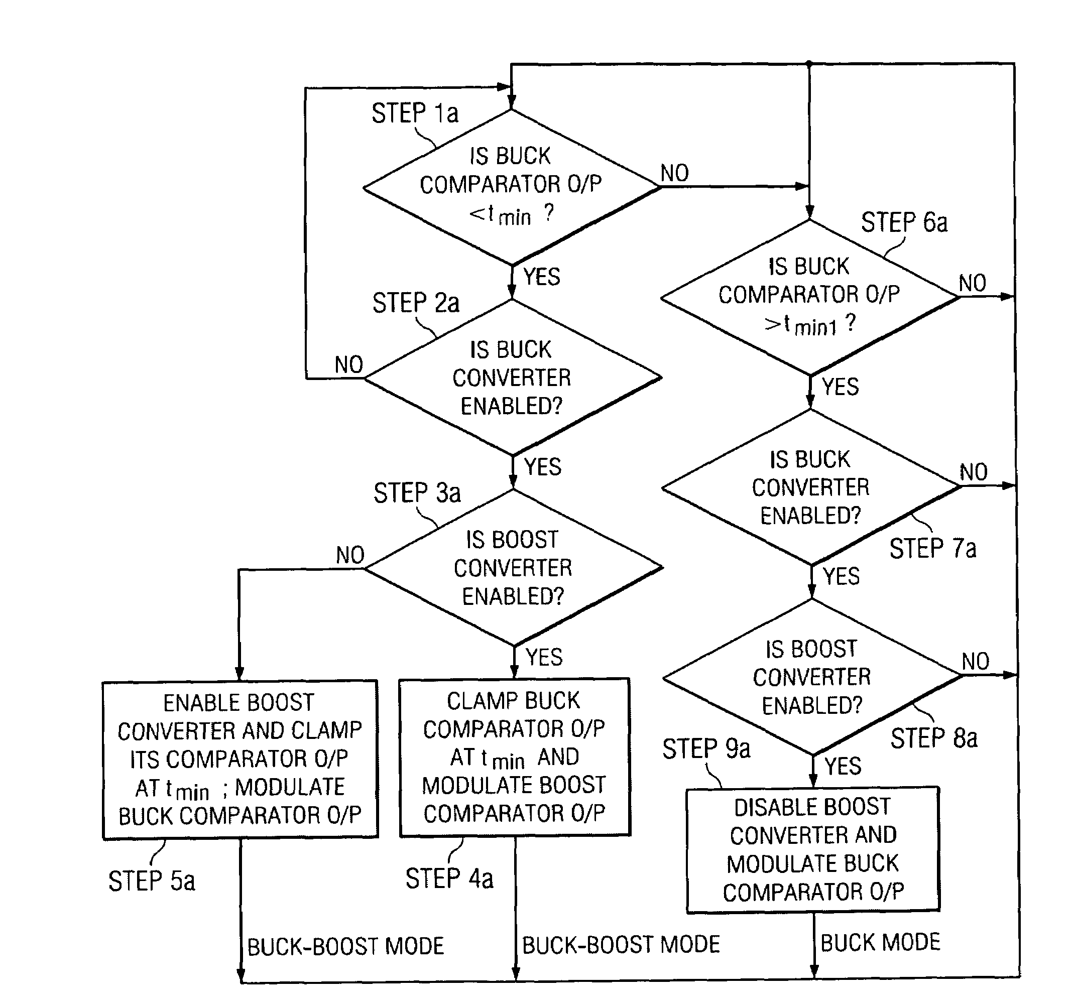
[0062]A method of and system for controlling a multiple switch node power converter that avoids switching subharmonics is disclosed. More particularly, a method of and system for controlling a multiple switch node power converter that does not require overlapping the boost and buck modulation ramps during buck-boost mode is disclosed.

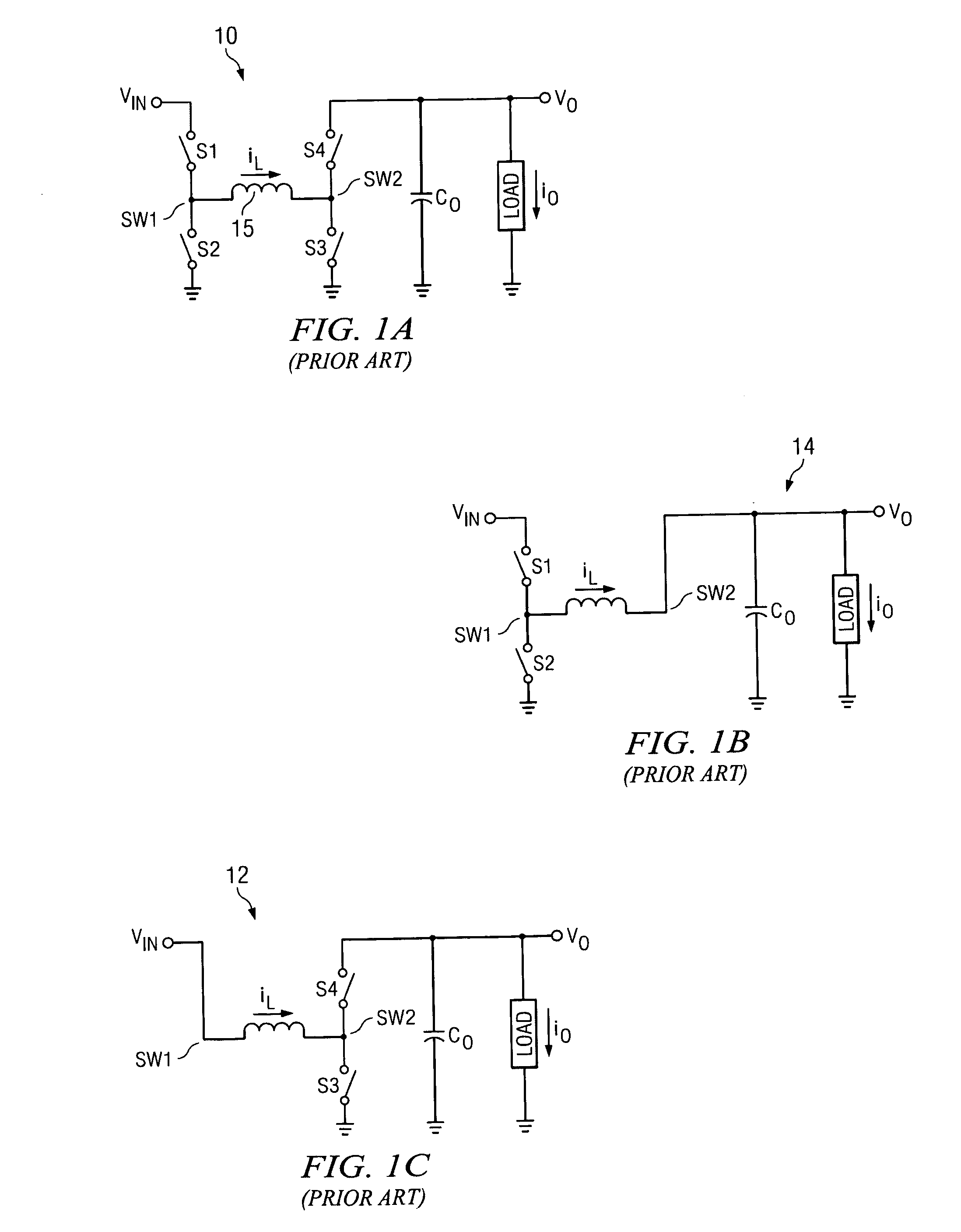
[0063]Buck-boost power conversion mode occurs when the input voltage, VIN, and the output voltage, VO, are equal or substantially equal in magnitude. In contrast with pure buck or pure boost modes in which the complementary switching pair at one switch node are switched ON and OFF during the switching cycle and the complementary switching pair at another switch node are not switched, i.e., either ON or OFF for the entire switching cycle, during buck-boost mode, the complementary switching pair at both switch nodes are switched ON and OFF during some portion of the switching cycle. However, advantageously, according to the present invention, only one of ...


PUM


Abstract

A method of and system for modulating buck and boost modulation ramps of a multiple switch node power converter without overlap. As the pulse width or duty cycle of the signal to a modulated complementary switching pair approaches a pre-established reference pulse width or duty cycle, plural fixed-width or fixed duty cycle pulses are generated and introduced to a nonmodulated complementary switching pair. A controller detects proximity to the pulse width or duty cycle limit and, correspondingly, initiates prematurely a pseudo-buck-boost mode in the power converter by generating fixed-width or fixed duty cycle pulses to the nonmodulated complementary switching pair while the duty cycles or pulse widths to the modulated complementary switching pair are still controlled by the appropriate modulation ramp. The net effect is that the power converter reaches its optimal operating point without overlap and eliminates any sub-harmonic switching.

Description

CROSS REFERENCE TO RELATED APPLICATIONS[0001]Not ApplicableSTATEMENT REGARDING FEDERALLY SPONSORED RESEARCH OR DEVELOPMENT[0002]Not ApplicableBACKGROUND OF THE INVENTION[0003]The present invention concerns multiple switch node power converters and, more particularly, to a method of and system for controlling the switching devices of multiple switch node power converters by modulating a single error voltage or current signal using only one of the modulation ramps at any given time.[0004]Referring to FIG. 1A, 1B, and 1C, a non-inverting, multiple switch node, four-switch buck-boost power converter 10 is shown. The buck-boost power converter 10 is structured and arranged to generate an output voltage, VO, that can be higher than, lower than, or equal to the input voltage, VIN. When the output voltage, VO, is greater than the input voltage VIN, the power converter 10 operates in boost mode 12, whereas when the input voltage, VIN, is greater than the output voltage, VO, the power convert...

Claims


Application Information

Patent Timeline
Patent Type & Authority Applications(United States)
IPC IPC(8): G05F1/00H03K7/08
CPCH03K17/16H02M3/1582
Inventor KESKAR, NEERAJ ARUNMILLER, PETER JAMES
Owner TEXAS INSTR INC
Why Eureka
Try Eureka