Circuitry to reduce PLL lock acquisition time

a technology of circuitry and phase lock, applied in the direction of oscillator tubes, pulse automatic control, electrical equipment, etc., can solve the problems of noise involved in switching from one loop gain to another, relative high loop gain, and generation of disabled, so as to reduce frequency/phase error, high loop gain, and rapid frequency acquisition lock

Active Publication Date: 2005-09-06
SEMICON COMPONENTS IND LLC
View PDF11 Cites 97 Cited by
  • Summary
  • Abstract
  • Description
  • Claims
  • Application Information

AI Technical Summary

Benefits of technology

[0011]In view of the foregoing background discussion, the present invention provides a phase lock loop employing multiple charge pumps, connected in parallel, to supply the input current of the low-pass filter in the PLL loop. When the magnitude of the oscillator frequency / phase error is large, all of the charge pumps are enabled driving reasonably high currents into the low pass filter, resulting in a relatively high loop gain. This provides a high slew rate for the oscillator control voltage to rapidly change the VCO output frequency to decrease the frequency / phase error and therefore provide a rapid frequency acquisition lock. As the error decreases, successive charge pumps are disabled until, with minimal error only a single pump supplies current to the filter. With this arrangement a filter with a fixed, narrow bandwidth can be used to provide both a fast loop response when the error is large and a slow response when the oscillator phase closely tracks the reference signal and any errors are small.

Problems solved by technology

When the magnitude of the oscillator frequency / phase error is large, all of the charge pumps are enabled driving reasonably high currents into the low pass filter, resulting in a relatively high loop gain.
Specifically, the noise involved in switching from one loop gain to another as the charge pumps are enabled or disabled is generated on the input side of the filter rather than within the filter itself.
In such an instance, the switching noise generated is subject to and thus attenuated by the filter itself.

Method used


Image

  • Circuitry to reduce PLL lock acquisition time
  • Circuitry to reduce PLL lock acquisition time
  • Circuitry to reduce PLL lock acquisition time

Examples


Embodiment Construction

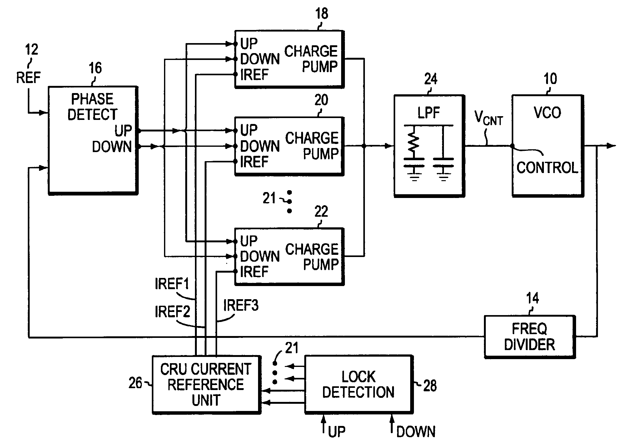
[0020]EMBODIMENT As shown in FIG. 1, a phase lock loop incorporating the invention includes a voltage-controlled oscillator (VCO) 10 whose output is to be phase-locked to a reference signal from a reference source 12. The output of the VCO 10 is applied to a frequency divider 14 whose output, in turn, is applied to the phase detector 16 that compares the frequency and phase of the divider 14 output with the frequency and phase of the reference signal 12. The output of detector 16 is an error signal, in this case separate UP and DOWN signals, that cause charge pumps 18, 20, 22 and any others 21 to deliver charge to, or remove charge from, a lower pass filter (LPF) 24. The output of the LPF 24 drives the VCO 10.

[0021]The circuit details of the phase detector, the low pass filter and the VCO are well known in the art and will be left in block form. For more information on these blocks see, for example, virtually any application note on the subject from many sources and the prior U.S. p...


PUM


Abstract

A phase locked loop, PLL, is described with multiple parallel charge pumps that are selectively disabled as phase lock is approached. A lock detection circuit is described that enabled reference currents to be fed to the parallel charge pumps. The error signal from a phase detector is arranged as UP and a DOWN signals that are averaged in the lock detector. When the average error is large, all the reference currents feed the charge pumps that provide a high loop gain to reduce the lock time. As the lock becomes closer selective reference currents are disabled to reduce loop gain so that a smooth transition to lock is made. Selectively switching currents into a low pass filter that usually follows a charge pump in a PLL circuit automatically reduces switching noise by the operation of the low pass filter.

Description

CROSS-REFERENCE TO RELATED APPLICATIONS[0001]The present application claims the benefit of U.S. Provisional Patent Application Ser. No. 60 / 447,423, which was filed on Feb. 14, 2003, of common title, inventorship and ownership, and which provisional application is hereby incorporated herein by reference.BACKGROUND OF THE INVENTION[0002]1. Field of the Invention[0003]This invention relates to a digital phase lock loop. More particularly it relates to a phase lock loop in which the effective loop gain and bandwidths are varied in accordance with the frequency / phase error.[0004]2. Background Information[0005]The invention is directed to digital phase lock loops commonly incorporated in large-scale integrated circuits. The operations performed by these circuits are synchronized to the output of a local clock and the clock in turn is often synchronized to an external reference clock so as to synchronize the operations of the circuit to those of other devices in a system that includes the ...

Claims


Application Information

Patent Timeline
Patent Type & Authority Patents(United States)
IPC IPC(8): H03L7/08H03L7/089H03L7/095H03L7/107H03L7/18H03L7/16
CPCH03L7/0898H03L7/095H03L7/107H03L7/18Y10S331/02H03L7/1075
Inventor MCDONALD, II, JAMES J.HULFACHOR, RONALD B.
Owner SEMICON COMPONENTS IND LLC
Why Eureka
Try Eureka