Check patentability & draft patents in minutes with Patsnap Eureka AI!

Light source unit and display device

a technology of light source unit and display device, which is applied in the direction of illuminated signs, display means, instruments, etc., can solve the problems of display quality deterioration, light leakage at the corners of the diffuser, and display quality deterioration, so as to prevent deterioration of display quality

Inactive Publication Date: 2010-01-28
SHARP KK
View PDF9 Cites 4 Cited by
  • Summary
  • Abstract
  • Description
  • Claims
  • Application Information

AI Technical Summary

Benefits of technology

[0009]In view of the above-mentioned state of the art, preferred embodiments of the present invention provide a light source unit and a display device, each capable of preventing deterioration of display qualities, caused by the “sagging” of the diffuser.
[0010]The present inventor made various investigations on a liquid crystal display device for TVs, which is getting larger. The inventor discovered that at a corner of a display region, display qualities are markedly deteriorated. As such deterioration of display qualities, a phenomenon in which a white portion is observed at four corners of the display region at the time of black state was observed. Then, the inventor discovered the following. Particularly in the case that a large-sized display panel is used, the “sagging” of the diffuser is markedly generated at corners of the display region, which causes light leakage at the corners of the diffuser. Therefore, the display qualities are deteriorated. Further, the inventor discovered that this deterioration of display qualities can be effectively prevented as follows. A holding member for holding down the diffuser on a diffuser-mounting base arranged within a light source chassis is arranged, thereby interposing a corner of the diffuser between the mounting base and the holding member. As a result of this unique arrangement and structure, the diffuser is prevented from warping and thereby, light leakage generated at the corner of the diffuser is sufficiently suppressed and minimized. As a result, the above-mentioned problems have been admirably solved, leading to development and completion of preferred embodiments of the present invention.

Problems solved by technology

The inventor discovered that at a corner of a display region, display qualities are markedly deteriorated.
Particularly in the case that a large-sized display panel is used, the “sagging” of the diffuser is markedly generated at corners of the display region, which causes light leakage at the corners of the diffuser.
Therefore, the display qualities are deteriorated.

Method used


Image

  • Light source unit and display device
  • Light source unit and display device
  • Light source unit and display device

Examples


embodiment 1

Preferred Embodiment 1

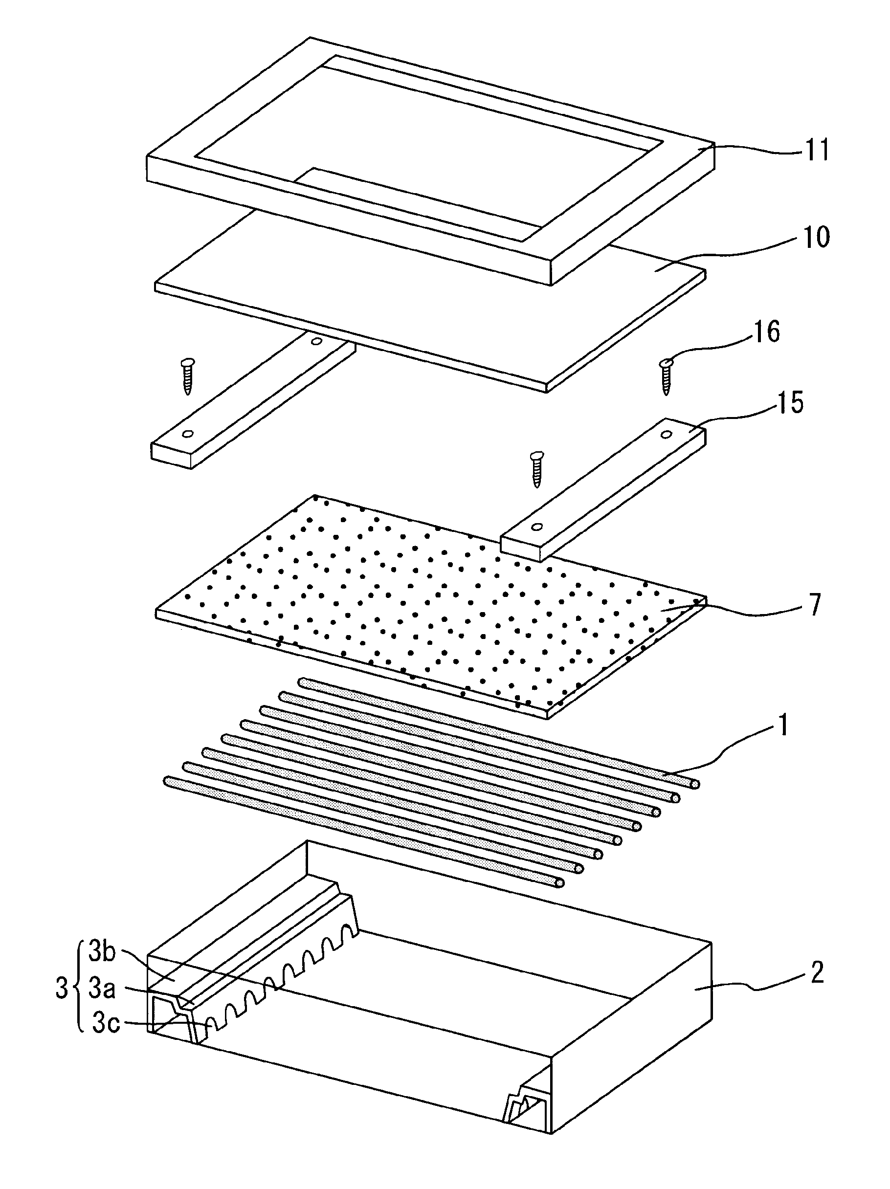
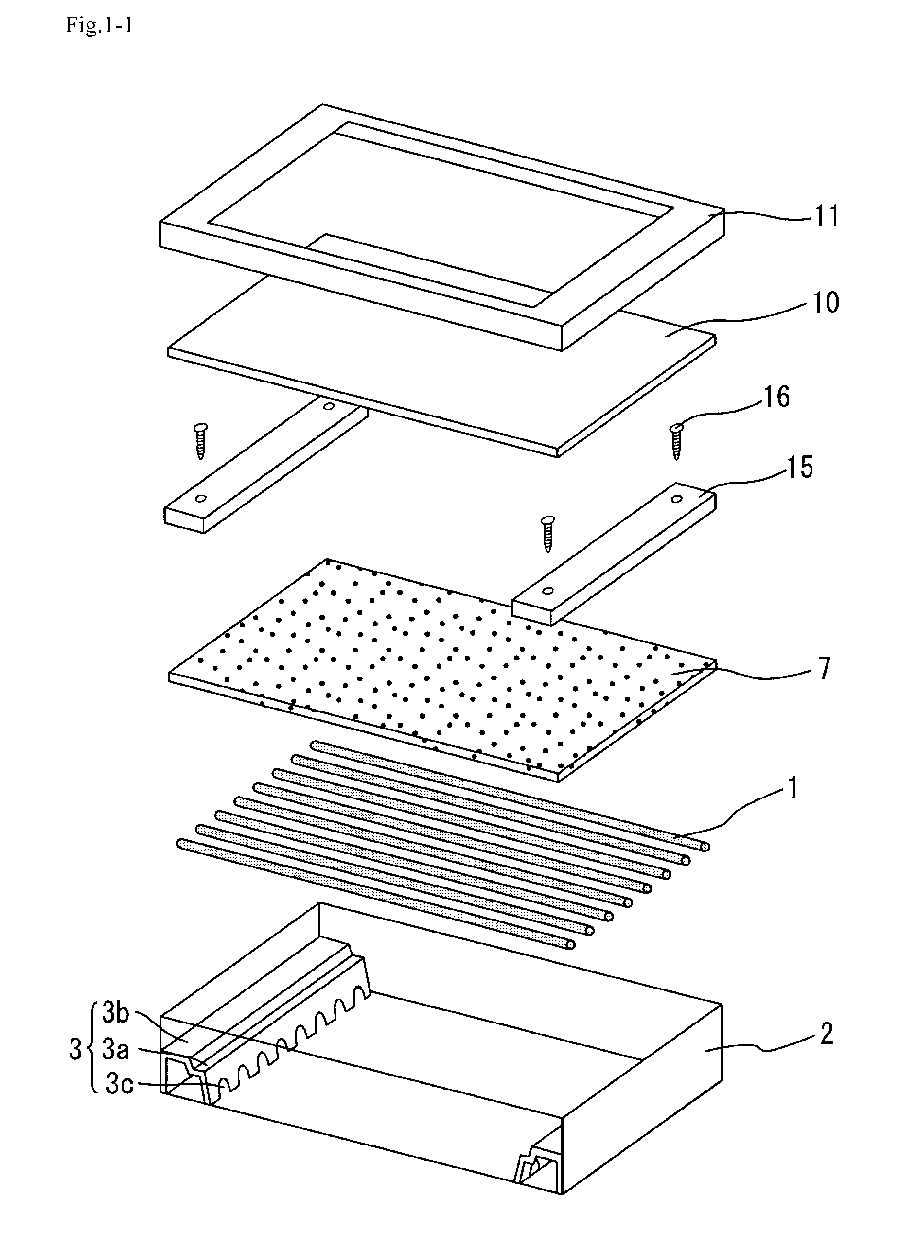
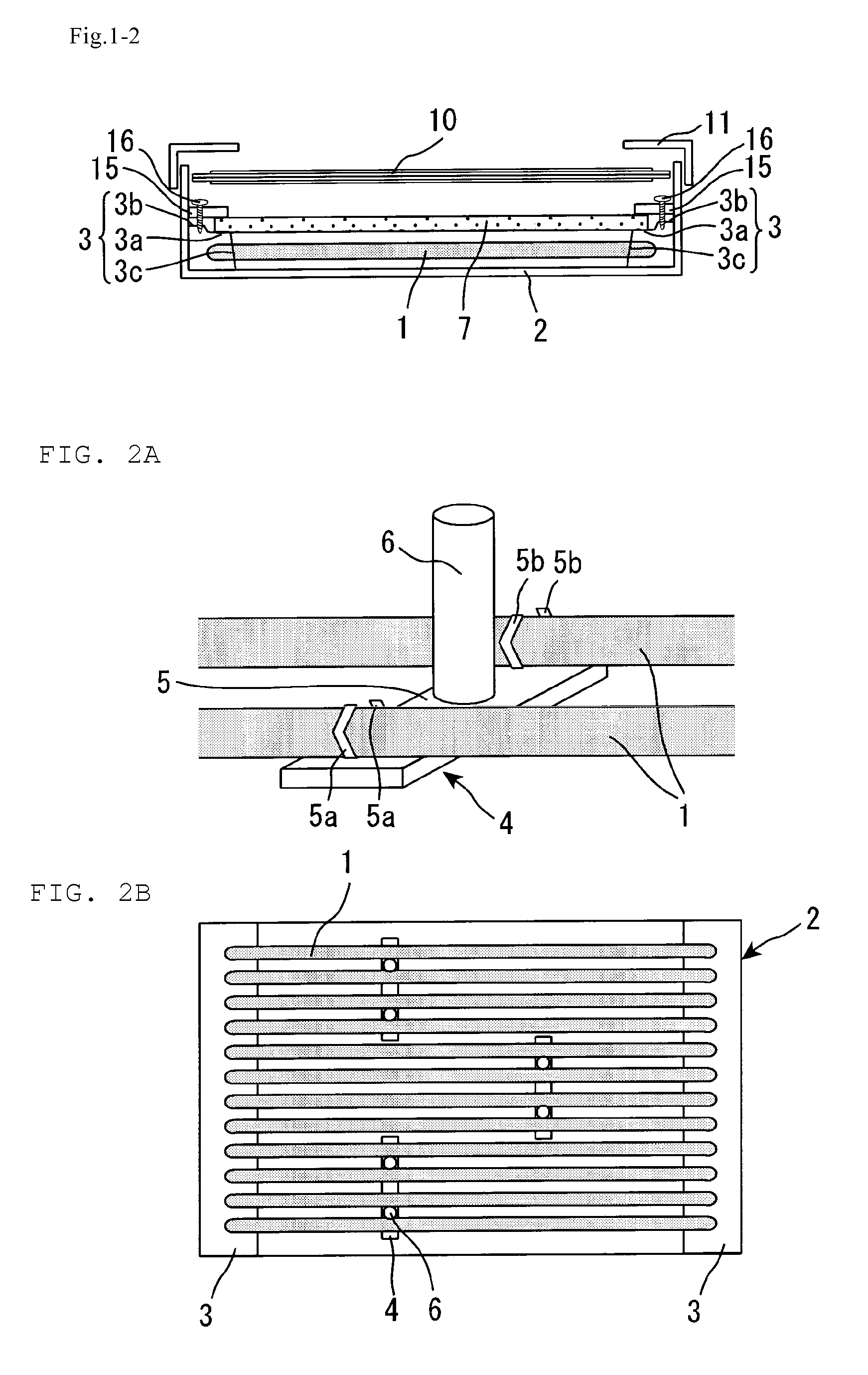
[0040]A light source unit according to Preferred Embodiment 1 is in accordance with one preferred embodiment of the light source unit of the present invention, and it can be used as a direct type backlight for liquid crystal display devices. FIG. 1-1 is a perspective exploded view schematically showing a configuration of a liquid crystal display device in accordance with Preferred Embodiment 1. FIG. 1-2 is a cross-sectional view schematically showing the configuration of the liquid crystal display device in accordance with Preferred Embodiment 1, as viewed in the direction perpendicular to the longitudinal direction of a linear light source.

[0041]As shown in FIGS. 1-1 and 1-2, the liquid crystal display device in Preferred Embodiment 1 preferably has a configuration in which a lower frame (light source chassis) 2, linear light sources 1, a plastic frame (mounting base) 3, a diffuser 7, a holding member 15, a screw 16, a liquid crystal panel 10, and an upper fra...

embodiment 2

Preferred Embodiment 2

[0057]A light source unit in Preferred Embodiment 2 is in accordance with another preferred embodiment of the light source unit of the present invention, and it can be used as a direct type backlight for liquid crystal display devices. FIG. 5 is a perspective view schematically showing an arrangement relationship among a plastic frame (mounting base), a diffuser, and a holding member in the backlight in accordance with Preferred Embodiment 2. The backlight in Preferred Embodiment 2 is the same as in Preferred Embodiment 1, except that the projection portion 3b of the plastic frame 3 is arranged to be above the level of the upper surface of the diffuser 7. That is, the backlight in Preferred Embodiment 2, covers the both ends of the light sources 1 which transversely penetrate the through-holes 3c, and the diffuser 7is mounted on the diffuser-mounted portion 3a. The projection portion 3b is arranged on the short sides of the diffuser 7 and also serves as a guide...

embodiment 3

Preferred Embodiment 3

[0059]A light source unit in Preferred Embodiment 3 is in accordance with another preferred embodiment of the light source unit of the present invention, and it can be used as a direct type backlight for liquid crystal display devices. FIG. 6 is a perspective view schematically showing an arrangement relationship among the plastic frame (mounting base), the diffuser, and the holding member in the backlight in accordance with Preferred Embodiment 3. The backlight in Preferred Embodiment 3 is the same as in Preferred Embodiment 1, except that the projection portion 3b of the plastic frame 3 is arranged to be at the same level of the upper surface of the diffuser 7. That is, the backlight in Preferred Embodiment 3, covers the both ends of the light sources 1 which transversely penetrate the through-holes 3c, and the diffuser 7 is mounted on the diffuser-mounted portion 3a. The projection portion 3b is arranged on the short sides of the diffuser 7 and also serves a...


PUM

PropertyMeasurementUnit
reflectanceaaaaaaaaaa
wavelengthaaaaaaaaaa
thicknessaaaaaaaaaa

Abstract

A light source unit prevents deterioration of display qualities, caused by “sagging” of a diffuser and includes a light source, a diffuser, and a light source chassis, the light source and the diffuser being arranged in this order from the bottom within the light source chassis. A mounting base is arranged below a corner of the diffuser, a holding member is arranged above the corner of the diffuser, the mounting base and the holding member are coupled with each other, and the diffuser is interposed between the mounting base and the holding member. The holding member preferably has a light-shielding property and the mounting base and the holding member are coupled with each other, with a screw, for example.

Description

BACKGROUND OF THE INVENTION[0001]1. Field of the Invention[0002]The present invention relates to a light source unit and a display device. More particularly, the present invention relates to a light source unit that is suitable for use as a direct type backlight in a liquid crystal display device, and a display device.[0003]2. Description of the Related Art[0004]The light source unit is used, for example, in a display device including a non-self-emission display panel. In a liquid crystal display device, for example, a liquid crystal panel itself does not emit light. Therefore, a transmissive or semi-transmissive liquid crystal display device is provided with a backlight which causes light to enter a liquid crystal panel.[0005]There are currently two different backlights used in a liquid crystal display device and the like: an edge light type (side light type) and a direct type. The direct type backlight has advantages in that it is suitably used in a large-sized display device and ...

Claims


Application Information

Patent Timeline
Patent Type & Authority Applications(United States)
IPC IPC(8): G02F1/13357F21V3/00
CPCG02F1/133604G02F2201/54G02F1/133608G02F1/133606
Inventor KAMADA, KENTARO
Owner SHARP KK
Features
  • R&D
  • Intellectual Property
  • Life Sciences
  • Materials
  • Tech Scout
  • Unparalleled Data Quality
  • Higher Quality Content
  • 60% Fewer Hallucinations
Learn More