Endoscope optical system device and endoscope with the same

a technology of optical system and endoscope, which is applied in the field of endoscope optical system device and endoscope with the same, can solve the problems of deteriorating poor observation visual field, and inability to apply an approach to adhere the moisture-resistant optical element, so as to prevent prevent the formation of condensation on the lens, and prevent the reduction of the picture quality of observed video image

Inactive Publication Date: 2010-01-28
FUJIFILM CORP
View PDF9 Cites 57 Cited by
  • Summary
  • Abstract
  • Description
  • Claims
  • Application Information

AI Technical Summary

Benefits of technology

[0030]According to the endoscope, the bright and clear image can be obtained.
[0031]According to the endoscope optical system device and the endoscope with the same, the joined surfaces of the first optical element and the second optical element are adhered together by the first adhesive, and peripheries of end portions of the joined surfaces are covered with the second adhesive with a moisture resistance. Therefore, such an event can be prevented without fail that the moisture seeps in the joined boundary from the outside via the peripheries of the end portions of the joined surfaces and then enters into the air layer that is formed between the first optical element and the second optical element. As a result, the formation of condensation on the lens can be prevented in advance, and also a reduction in picture quality of the observed video image can be prevented.

Problems solved by technology

During the inspection, sometimes contaminants such as body fluids, or the like adhere to the lens, which is arranged at the top end of the inserting portion to expose to the outside, and thus the observation visual field becomes poor.
Therefore, such a problem existed that a picture quality of the observed video image deteriorates.
Therefore, it is impossible to say that the sufficient hermetic sealing can always be kept by merely adhering these narrow joined surfaces 29, and sometimes the moisture is ready to enter into the air layer S. Also, in some cases the above approach cannot be applied to adhere the moisture-resistant optical element whose moisture permeability is low but which cannot be used because of its low adhesive strength.

Method used


Image

  • Endoscope optical system device and endoscope with the same
  • Endoscope optical system device and endoscope with the same
  • Endoscope optical system device and endoscope with the same

Examples


first embodiment

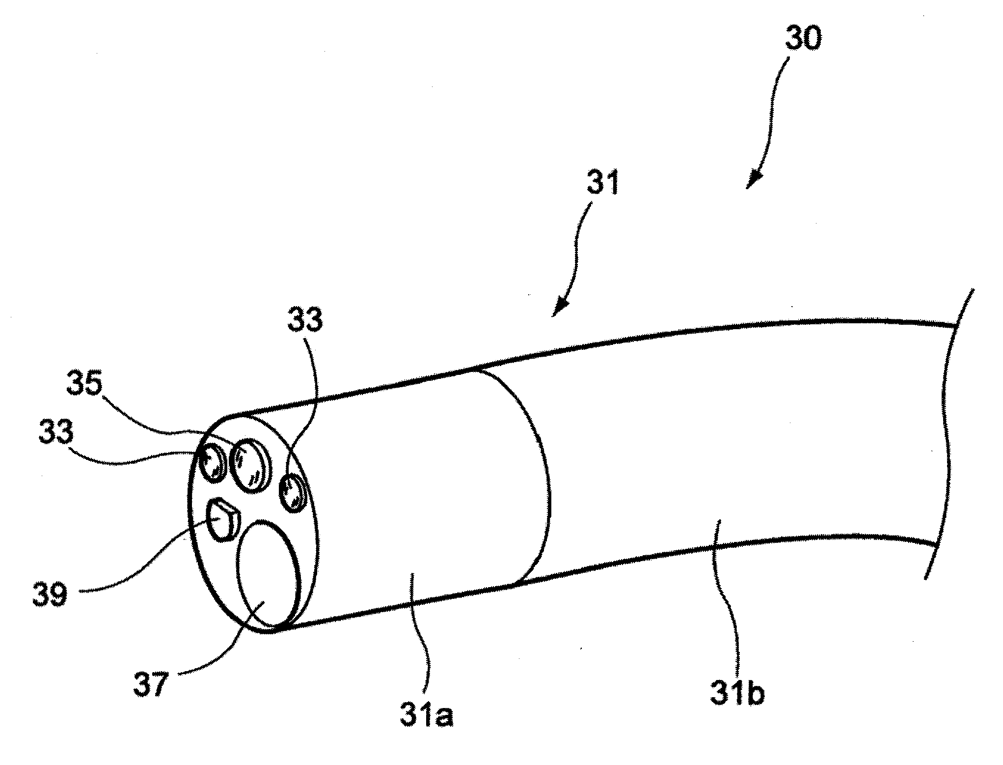
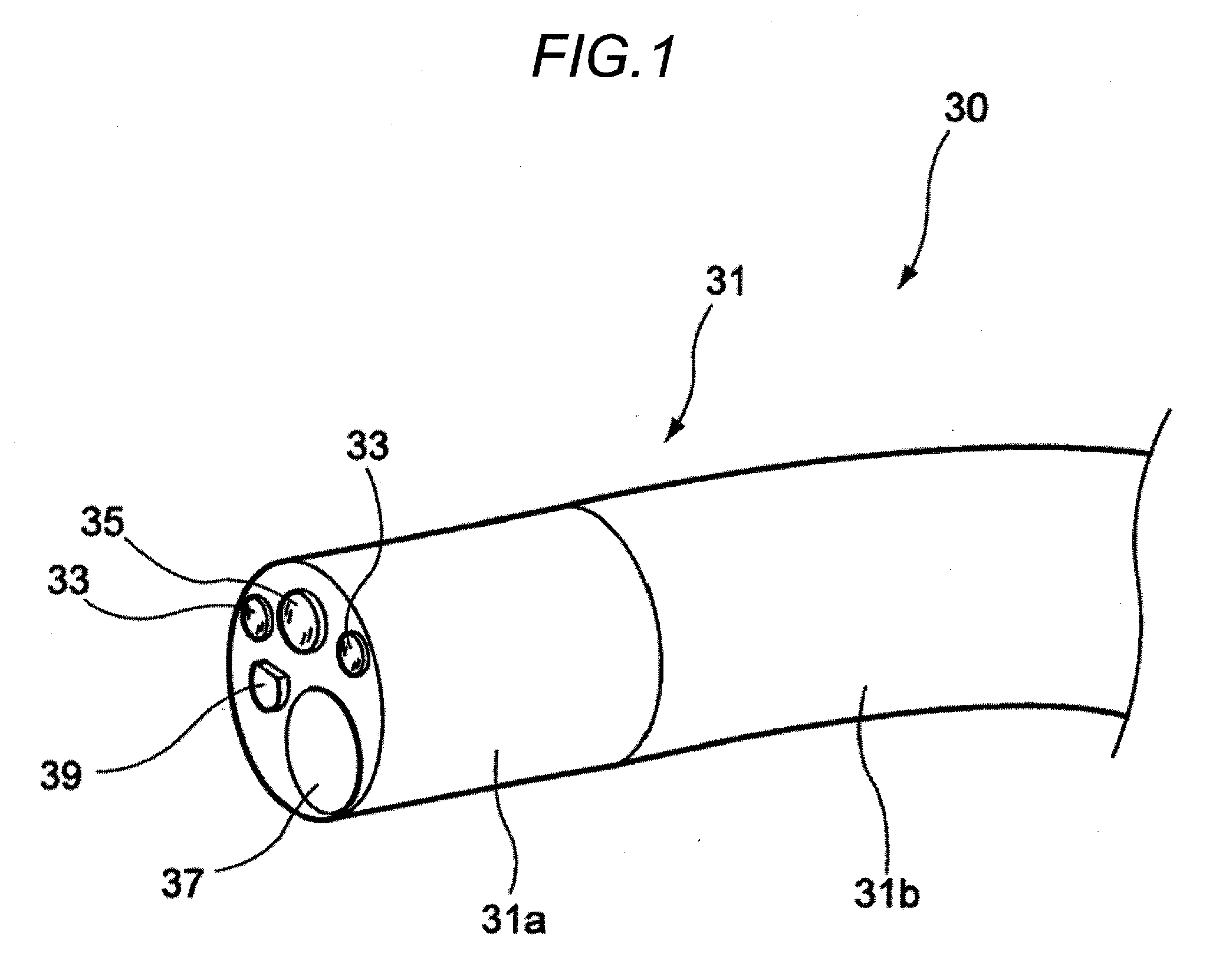
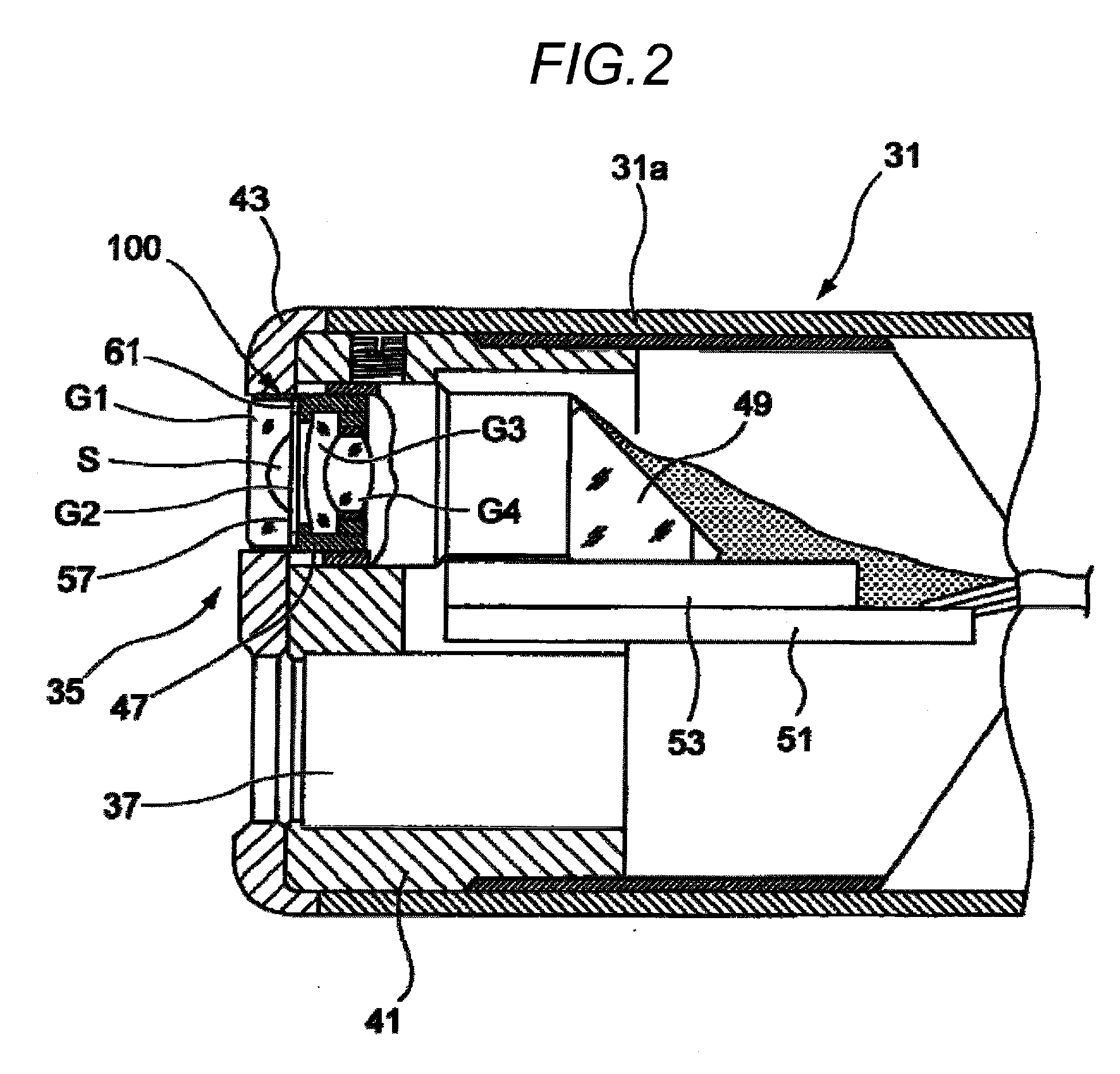
[0041]FIG. 1 is an external perspective view showing a top end portion of an inserting portion of an endoscope, FIG. 2 is a sectional view of a lens device of the endoscope shown in FIG. 1, and FIG. 3 is a longitudinal sectional view showing a configuration of an objective optical system.

[0042]As shown in FIG. 1 to FIG. 3, an inserting portion 31 of an endoscope 30 inserted in the body cavity, or the like has a top end hard portion 31a whose top end portion is formed of a hard material. An angle portion 31b that can operate the top end hard portion 31a in a desired direction while being bent is connected at the back of the top end hard portion 31a. An illumination window 33 and an observation window 35 are provided to a top end surface (although not shown, a side surface of a laterally viewing type endoscope) of the top end hard portion 31a, and a treating-tool passing channel 37 for passing a treating tool such as a forceps, or the like through there is opened on the top end surfac...

second embodiment

[0060]Next, an optical system device according to a second embodiment will be explained with reference to FIG. 5 hereunder. FIG. 5 is a pertinent sectional view of an optical system device applied to an illumination unit as an illuminating unit. In this case, in the optical system device according to the second embodiment, an optical element arranged at the back of the parallel plate (second optical element) is different from the optical element in the first embodiment. Remaining elements are similar to the optical system device in the first embodiment, and therefore their explanation will be omitted or simplified by affixing the same or equivalent reference symbols to the same portions.

[0061]As shown in FIG. 5, in an illumination unit 200 as an optical system device in the second embodiment, the first lens G1 and the parallel plate G2 are arranged in the illumination window 33 that is provided to the top end of the inserting portion 31. Like the optical system device in the first e...


PUM


Abstract

Out of optical elements that are provided to the top end side of an inserting portion of an endoscope, a first optical element arranged closest to an observation object side and a second optical element joined hermetically to the first optical element via an air layer are joined at joined surfaces by a first adhesive. Also, peripheries of end portions of the joined surfaces are covered with a second adhesive whose moisture permeability is lower than the first adhesive.

Description

[0001]The present application claims priority from Japanese Patent Application No. 2008-188186 filed on Jul. 22, 2008, the entire content of which is incorporated herein by reference.BACKGROUND OF INVENTION[0002]1. Field of the Invention[0003]The present invention relates to an endoscope optical system device having an optical system which is provided on the top end side of an inserting portion of an endoscope and in which a plurality of optical elements are aligned, and an endoscope with the same.[0004]2. Description of the Related Art[0005]An endoscope used to observe / inspect a body cavity, or the like is equipped with an illuminating unit and an observing unit at an inserting portion that is inserted into the body cavity, or the like. The illuminating unit has a light guide for transmitting an illumination light emitted from a light source device. An illumination lens, from which the illumination light fed from the light guide is emergent, is fitted to a top end of the inserting ...

Claims


Application Information

Patent Timeline
Patent Type & Authority Applications(United States)
IPC IPC(8): A61B1/06
CPCA61B1/0008A61B1/00096G02B23/243G02B7/025A61B1/127
Inventor TAKAHASHI, KAZUAKIKITANO, RYOUYASHIRO, TAKASHIYAMAMOTO, GOKI
Owner FUJIFILM CORP
Why Eureka
Try Eureka