Display apparatus

a technology of display apparatus and display screen, which is applied in the field of display screen, can solve problems such as uneven display, and achieve the effect of reducing uneven display screen more reliably

Active Publication Date: 2020-12-29
SEIKO EPSON CORP
View PDF20 Cites 2 Cited by
  • Summary
  • Abstract
  • Description
  • Claims
  • Application Information

AI Technical Summary

Benefits of technology

[0006]An advantage of some aspects of the embodiment is to provide a display apparatus that can suppress the display unevenness from being visually recognized.
[0009]According to the display apparatus in an aspect of the embodiment, since the mirror angle β is set so as to satisfy the Expressions (1), (2), and (3), the error in the number of mirrors can be reduced, and thus, it is possible to reduce the display unevenness. In addition, by satisfying the Expressions (1), (2), and (3) described above, both the loss of the image light and the occurrence of a double image (ghost) are suppressed, and thus, a bright and clear image can be obtained.
[0011]According to this configuration, it is possible to provide a highly practical display apparatus.
[0013]An advantage of some aspects of the embodiment is that the display unevenness can be more reliably reduced.

Problems solved by technology

However, there is a problem in that a display unevenness caused by the plurality of mirrors or the reflection surfaces positioned in front of the eyes of the observer is visually recognized.

Method used


Image

  • Display apparatus
  • Display apparatus
  • Display apparatus

Examples


Embodiment Construction

lass="d_n">[0030]Hereinafter, an embodiment will be described using the drawings.

[0031]The display apparatus in the present embodiment is used as, for example, a head mount display.

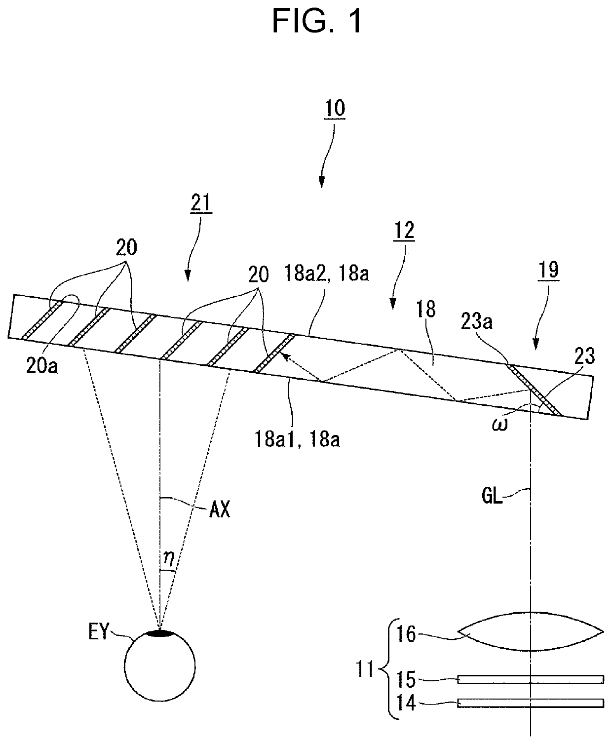
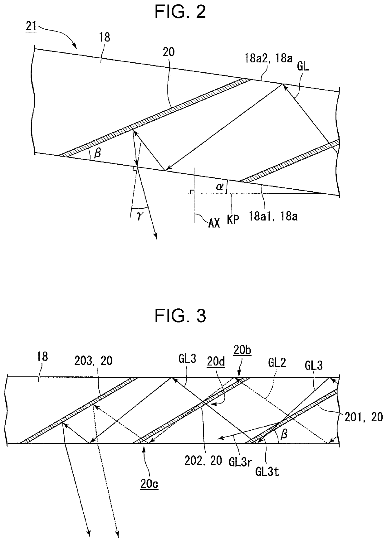
[0032]FIG. 1 is a plan view of a display apparatus in an embodiment. FIG. 2 is an enlarged view of an emission portion.

[0033]In the following drawings, in order to make each configuration element easier to see, the scales of dimensions may be different from each other depending on the configuration elements.

Overall Configurations of the Light Guide Device and the Display Apparatus

[0034]As illustrated in FIG. 1, the display apparatus 10 includes an image forming device 11 and a light guide device 12. The display apparatus 10 causes an observer to visually recognize the display image as a virtual image and causes the observer to observe the external image in a see-through manner. In the display apparatus 10, a pair of image forming devices 11 and light guide devices 12 are provided corresponding to the righ...


PUM

PropertyMeasurementUnit
light guide angleaaaaaaaaaa
refractive indexaaaaaaaaaa

Abstract

A display apparatus includes an image forming device and a light guide. The light guide includes an incident portion and an emission portion including a plurality of mirrors. In the light guide, the total reflection surface is disposed to be inclined with respect to a virtual plane perpendicular to a visual axis, and the mirrors are disposed to be inclined with respect to the total reflection surface. The mirror angle is set such that the light guide angle, the mirror angle, the light angle, the limit incidence angle, and the refractive index of the light guide satisfy the predetermined relationship.

Description

BACKGROUND1. Technical Field[0001]The present disclosure relates to a display apparatus.2. Related Art[0002]Recent years, as one of wearable information devices, an image display apparatus in a type of being worn on the head of an observer such as a head mount display is provided. In addition, an image display apparatus capable of simultaneously and visually recognizing both an image generated by a display element and an image of the outside of the observer when the observer wears the image display apparatus, a so-called see-through type image display apparatus is known.[0003]In JP-A-2012-42654, a display apparatus is disclosed, which includes an image forming device, a collimating optical system for collimating light from the image forming device, a light guide optical device for guiding and emitting the light from the collimating optical system, and a moving device for relatively moving an optical axis of the image forming device and an optical axis of the collimating optical syst...

Claims


Application Information

Patent Timeline
Patent Type & Authority Patents(United States)
IPC IPC(8): G02B27/01G02B6/00F21V8/00
CPCG02B27/0172G02B6/0031G02B6/0055G02B2027/0178G02B2027/0125
Inventor YOSHIDA, SHOHEI
Owner SEIKO EPSON CORP
Why Eureka
Try Eureka