Layered Electrode Array and Cable

a technology of electrode arrays and cables, applied in the direction of external electrodes, printed circuit aspects, sensors, etc., can solve the problems of high manufacturing cost, partial or total malfunction of implants, high manufacturing cost, etc., and achieve long-term stability and reliable implanting

Inactive Publication Date: 2010-01-28
MED EL ELEKTROMEDIZINISCHE GERAETE GMBH
View PDF7 Cites 36 Cited by
  • Summary
  • Abstract
  • Description
  • Claims
  • Application Information

AI Technical Summary

Benefits of technology

[0032]A further objective of the invention is to provide an implantable medical assembly which can be reliably implanted with long term stability.
[0033]A still further objective is to provide an implantable medical assembly which has more stable mechanical and electrical characteristics.
[0035]A yet further objective of the present invention is to provide an implantable medical assembly which is easier to manufacture.
[0041]Implantable nerve stimulators, by utilizing a fluoropolymer film as the insulating material, can typically occupy less space than conventional nerve stimulators that use silicone as a carrier for the electrode array. The reduced space provided by fluoropolymer film structures make them especially suitable for use in small medical products such as neurostimulation devices used to help restore or maintain some degree of lost sensory or motor function in neurologically impaired individuals. In addition, implantable nerve stimulator structures utilizing fluoropolymers can be highly reliable because of the excellent insulating capacity of the material, its lack of chemical or biochemical reactivity and its mechanical stability.

Problems solved by technology

Further, many neurostimulation devices require a large number of electrodes placed in close proximity to neural structures to facilitate effective stimulation.
If only one conduction wire is fractured, partial or total malfunction of the implant may result.
As such, manufacturing such devices to ensure that they are reliable and sturdy is a specialized craft, and requires much time and expense.
Ensuring that the wiring and connections of the various components of the systems occurs correctly is often the most expensive and labor intensive aspect of the manufacturing process and can result in high manufacturing costs particularly if such devices need to be specifically hand made.
While the manual method has proven relatively successful to date, it has an intensive labor component and hence is a relatively expensive process.

Method used


Image

  • Layered Electrode Array and Cable
  • Layered Electrode Array and Cable
  • Layered Electrode Array and Cable

Examples


Embodiment Construction

[0057]The following describes the best mode presently contemplated for carrying out the invention. This description is not to be taken in a limiting sense, but is made merely for describing the general principles of the invention. The scope of the invention should be determined with reference to the claims.

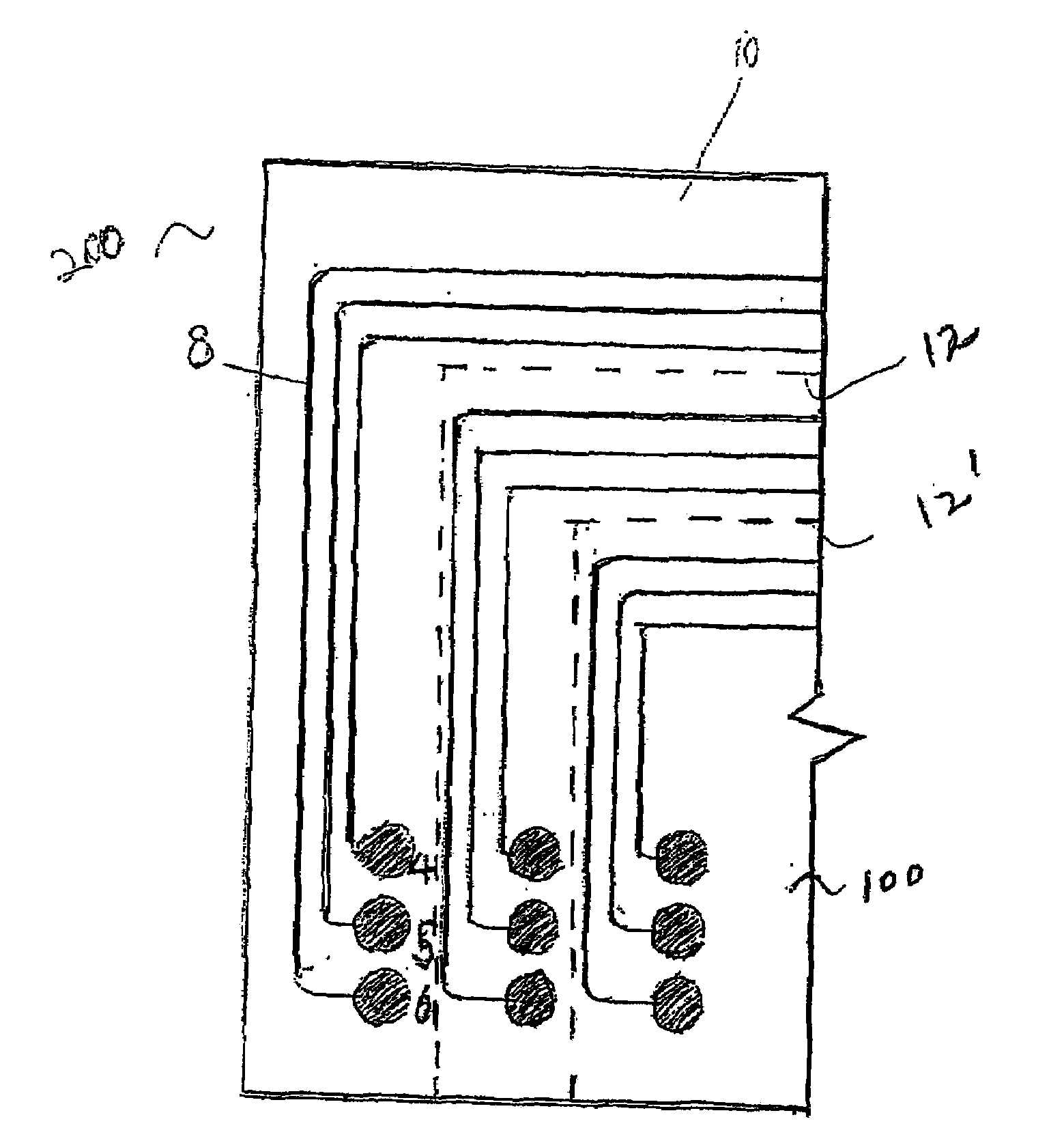
[0058]FIG. 5 shows a planar view of a preferred embodiment of an implantable medical assembly with electrodes and conduction wires according to the present invention. The aforementioned implantable medical assembly is designed to carry electrical signals from the housing that contains the electrical stimulator to the electrodes of an implantable nerve stimulation device for the purpose of safely and reliably stimulating human nerves. According to an implantable medical assembly 200, shown in FIG. 5, conduction wires 8 continuous with electrodes 4, 5 and 6 are embedded within a suitable biocompatible material 100, such as FEP film. The wires 8 and electrodes 4, 5, and 6 are formed ...


PUM

PropertyMeasurementUnit
thicknessaaaaaaaaaa
widthaaaaaaaaaa
thicknessaaaaaaaaaa

Abstract

A method of fabricating a neurostimulation circuit is disclosed. According to the present invention, individual implantable assembly layers are cut by a laser or by mechanical means, and then stacked together, thereby providing a more efficient manufacturing method for manufacturing high density implantable electrode arrays and cables. In the invention, the separate implantable assembly layers can be melted and conglomerated to form a neurostimulation circuit in which the conductors and terminal pads are encapsulated within a continuous polymer insulating film.

Description

FIELD OF THE INVENTION[0001]The present invention relates to an implantable medical assembly having a biologically compatible film within which at least one electrode and at least one conduction wire connected to the electrode to provide the stimulation signal for human nerves are embedded, and more particularly to the design of the conduction wires embedded in the biologically compatible film. More particularly, the present invention relates to a method of forming electrode arrays, such as arrays for sensors, including biosensors, and implantable devices, such as an implantable recording or stimulating electrodes or leads for use in the body.BACKGROUND OF THE INVENTION[0002]For several years, researchers have been attempting to establish communications through living neurons. It is now well known that electrical stimulation of certain nerves and certain regions of the brain can be used to convey information which can no longer be provided by a person's own eyes or ears, stimulate p...

Claims


Application Information

Patent Timeline
Patent Type & Authority Applications(United States)
IPC IPC(8): A61N1/05H01R43/00
CPCA61B5/04001Y10T29/49117A61B2562/043A61B2562/046A61B2562/125A61N1/0541H05K1/028H05K1/0298H05K1/118H05K3/0052H05K3/4611H05K3/4635H05K2201/0909H05K2201/09845H05K2203/065A61B2562/0209A61B5/24A61N1/375
Inventor SPRUIT, ARJEN
Owner MED EL ELEKTROMEDIZINISCHE GERAETE GMBH
Why Eureka
Try Eureka