Method and device for gluing the free edge of a log of web material in a rewinding machine

a technology of free edge and rewinding machine, which is applied in the direction of thin material processing, transportation and packaging, and article delivery. it can solve the problems of increasing the dimensions of the line, the risk of the outermost turn of the log becoming unwound, and the cost of the line increasing

Inactive Publication Date: 2010-02-04
FABIO PERINI SPA
View PDF5 Cites 11 Cited by
  • Summary
  • Abstract
  • Description
  • Claims
  • Application Information

AI Technical Summary

Benefits of technology

[0031]In a possible embodiment, the glue dispenser comprises a rotating roller arranged along the feed path of the web material and on one side thereof. The roller can have a substantially cylindrical surface, for example engraved according to inclined helical lines which intersect to define truncated-pyramid shaped protuberances. With this structure, similar to that of an embossing roller, a surface engraving pattern

Problems solved by technology

If this edge were not secured by gluing, in the steps subsequent to rewinding there would be the risk of the outermost turns of the log becoming unwound, with consequent risks of malfunction of the line or even causing its shutdown.
The presence of these gluing machines implies an increase in the dimensions of the line and an increase in its cost, also in view of the fact that in certain cases a single rewinding machine must be combined with a double gluing machine, due to the different production speeds of these two machines.
It may also be necessary to provide an intermediate storage area between the rewinding machine and the gluing machine, which in turn increases the cost and dimensions of the line.
Nonetheless, these solutions have some limits prevalently related to the reduced speed at which these machines are able to operate due to the risk of sprays of glue forming if the mechanical glue distribution members are operated at excessive speeds.
The use of gluing nozzles also has some drawbacks, in particular related to the poor precision with which glue is applied.
Moreover, the need to operate the glue dispenser intermittently causes further constructional and control difficulties.
A further difficulty lies in the fact that the log on which the final edge has been wound is not subjected to high p

Method used


Image

  • Method and device for gluing the free edge of a log of web material in a rewinding machine
  • Method and device for gluing the free edge of a log of web material in a rewinding machine
  • Method and device for gluing the free edge of a log of web material in a rewinding machine

Examples


Embodiment Construction

OF EMBODIMENT OF THE INVENTION

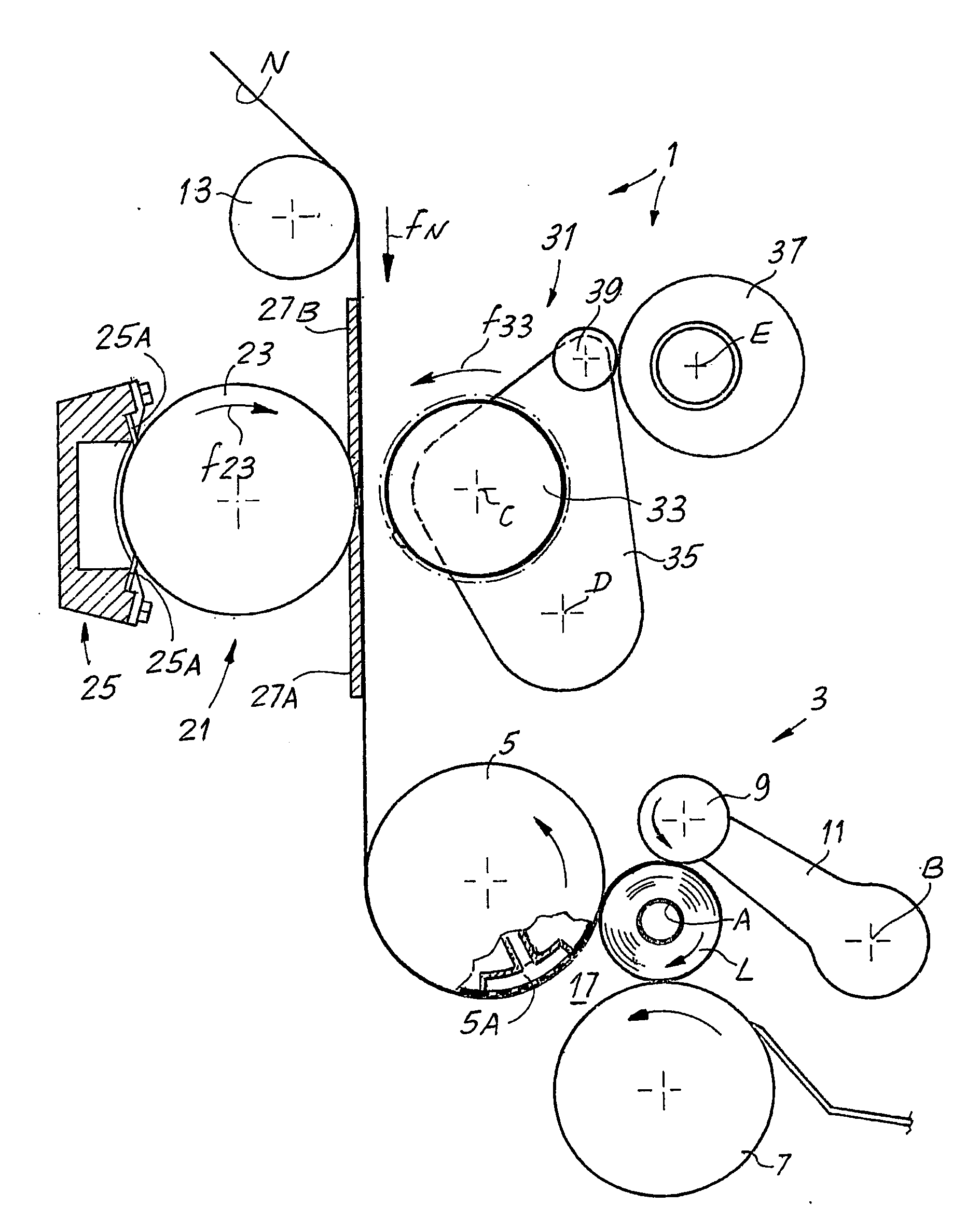
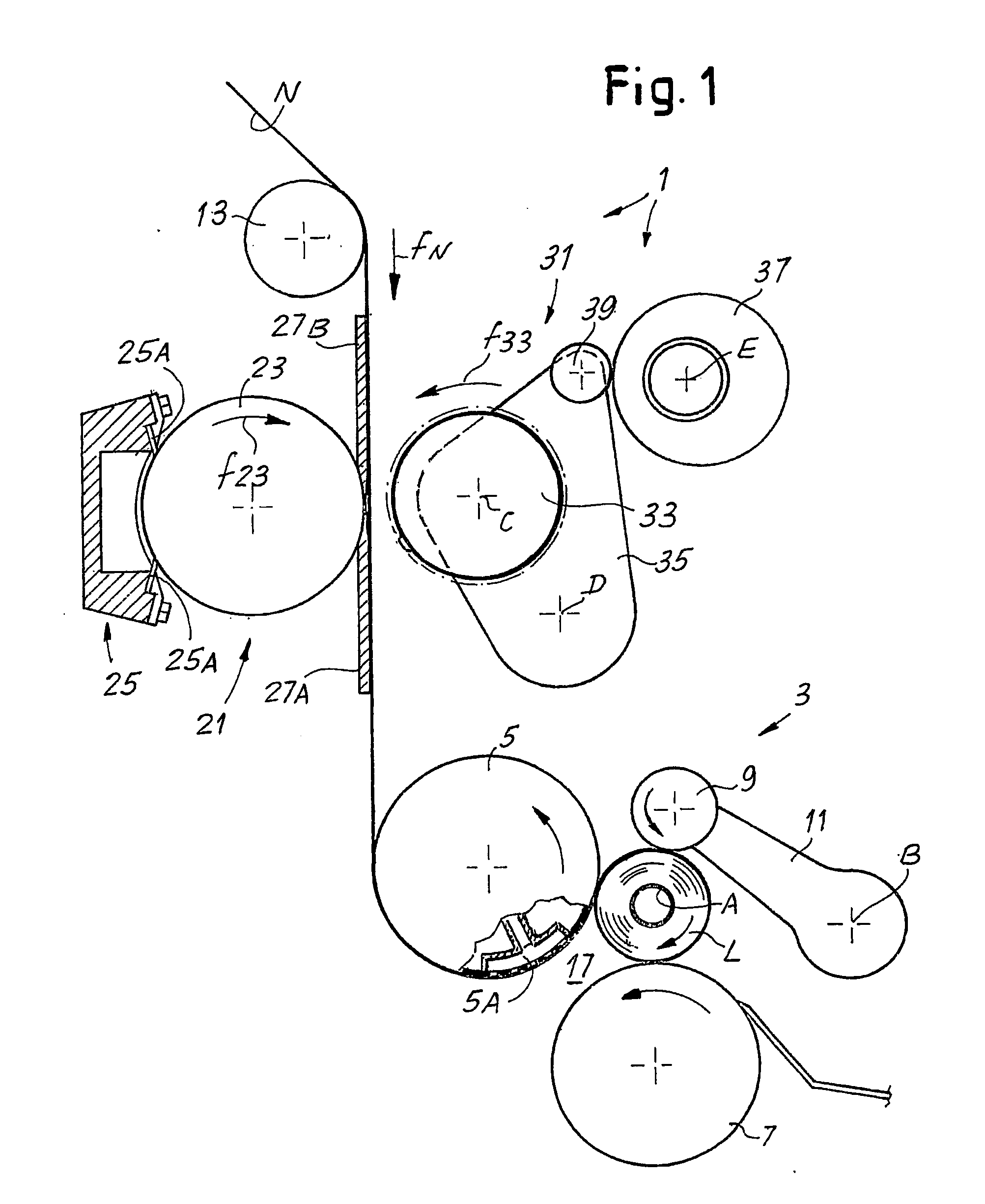
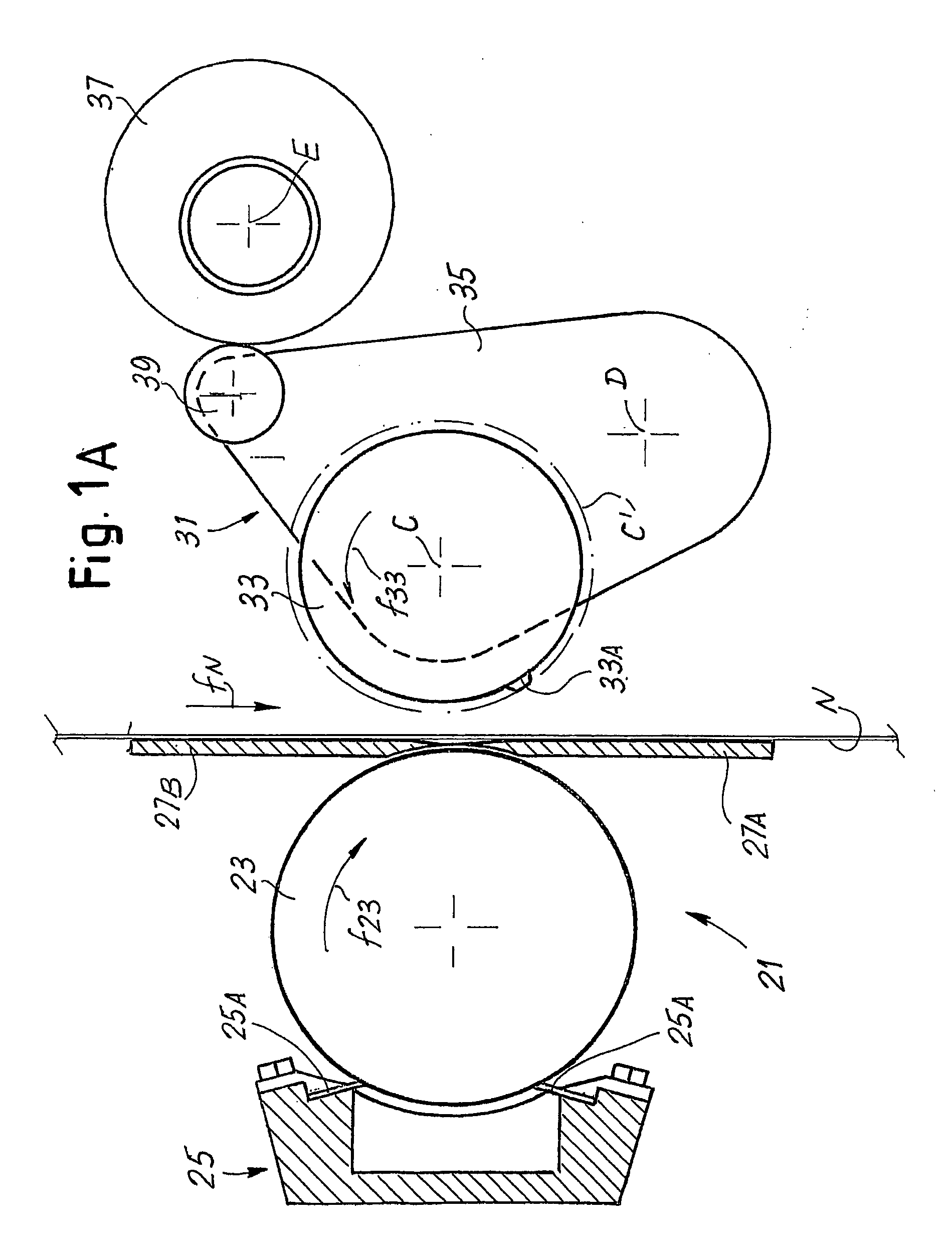
[0045]FIGS. 1, 1A, 2, 2A, 3 and 4 show a first embodiment of a rewinding machine according to the invention and of the relative operating method. With reference to these figures, reference number 1 generally indicates a rewinding machine comprising a winding unit 3 for forming logs L of a web material N. In an advantageous embodiment the logs L are formed around winding cores A, cylindrical in shape and preferably tubular, although it would also be possible to apply the invention to rewinding machines that form logs without a winding core, or in which the winding core is only present during forming of the log and is then removed to be recycled. Moreover, the shape of the winding core can differ from cylindrical.

[0046]In an advantageous embodiment the winding unit 3 comprises a first winding roller 5, a second winding roller 7 and a third winding roller, or moving winding roller 9, supported by arms 11 oscillating about an axis B, substantially parallel ...


PUM

PropertyMeasurementUnit
Flexibilityaaaaaaaaaa
Speedaaaaaaaaaa
Circumferenceaaaaaaaaaa

Abstract

A rewinding machine for producing logs of web material is described which includes a winding unit; a feed path of the web material towards the winding unit; a severing device to sever the web material upon completion of winding each log; and a glue dispenser to apply a glue to the web material. The machine also includes a diverter member disposed and controlled to temporarily divert the web material towards the glue dispenser.

Description

TECHNICAL FIELD[0001]The present invention relates to a method for producing logs of web material. In a particular embodiment, the invention relates to a method and to a machine for producing logs of web material with a glued edge.STATE OF THE ART[0002]In the field of converting of tissue paper and of other materials in web form it is often necessary to wind a web material from a parent reel or from another source of material into logs of suitable dimensions.[0003]In particular, in the field of production of rolls of toilet paper, paper towels for domestic and industrial use and other similar products, tissue paper is produced by continuous machines with a dry or wet system and wound in large parent reels. These are subsequently unwound feeding the web material to a rewinding machine which, from a single reel or from several plies fed from several reels unwound in parallel, produces a plurality of logs with a diameter equal to the diameter of the finished product to be placed on the...

Claims


Application Information

Patent Timeline
IPC IPC(8): B65H19/29B65H19/26B65H19/28
CPCB65H19/29B65H2301/414421B65H2408/235B65H2301/414443B65H2301/414436
Inventor GELLI, MAUROMADDALENI, ROMANOMAZZACCHERINI, GRAZIANO
Owner FABIO PERINI SPA
Why Eureka
Try Eureka