Check patentability & draft patents in minutes with Patsnap Eureka AI!

Digital signal decoding method

a digital signal and decoding technology, applied in the field of decoding methods, can solve problems such as incorrect decoding of logical codes

Inactive Publication Date: 2010-02-04
HONG FU JIN PRECISION IND (SHENZHEN) CO LTD +1
View PDF1 Cites 0 Cited by
  • Summary
  • Abstract
  • Description
  • Claims
  • Application Information

AI Technical Summary

Benefits of technology

The present patent is about a digital signal decoding method that can correctly decode a digital signal even if the frequency of the signal is unstable. The method uses a ratio relationship between low and high voltage periods of the signal to determine the logical value of the signal. This allows for accurate decoding even if the frequency of the signal is not stable. The method also includes steps to read the voltage periods of the signal, compute the ratio, and compare it with predetermined values to determine the logical value of the signal. The method can be used in various applications such as remote control television.

Problems solved by technology

If the collected voltage is at the high level (shown at a broken line of the upper schematic view), the digital signal is decoded as logical “1.” If the collected voltage is at the low level (shown at a broken line of the lower schematic view), the digital signal is decoded as logical “0.” However, if the frequency of the digital signal is unstable, the decoded logical codes maybe not correct.

Method used


Image

  • Digital signal decoding method
  • Digital signal decoding method
  • Digital signal decoding method

Examples


Embodiment Construction

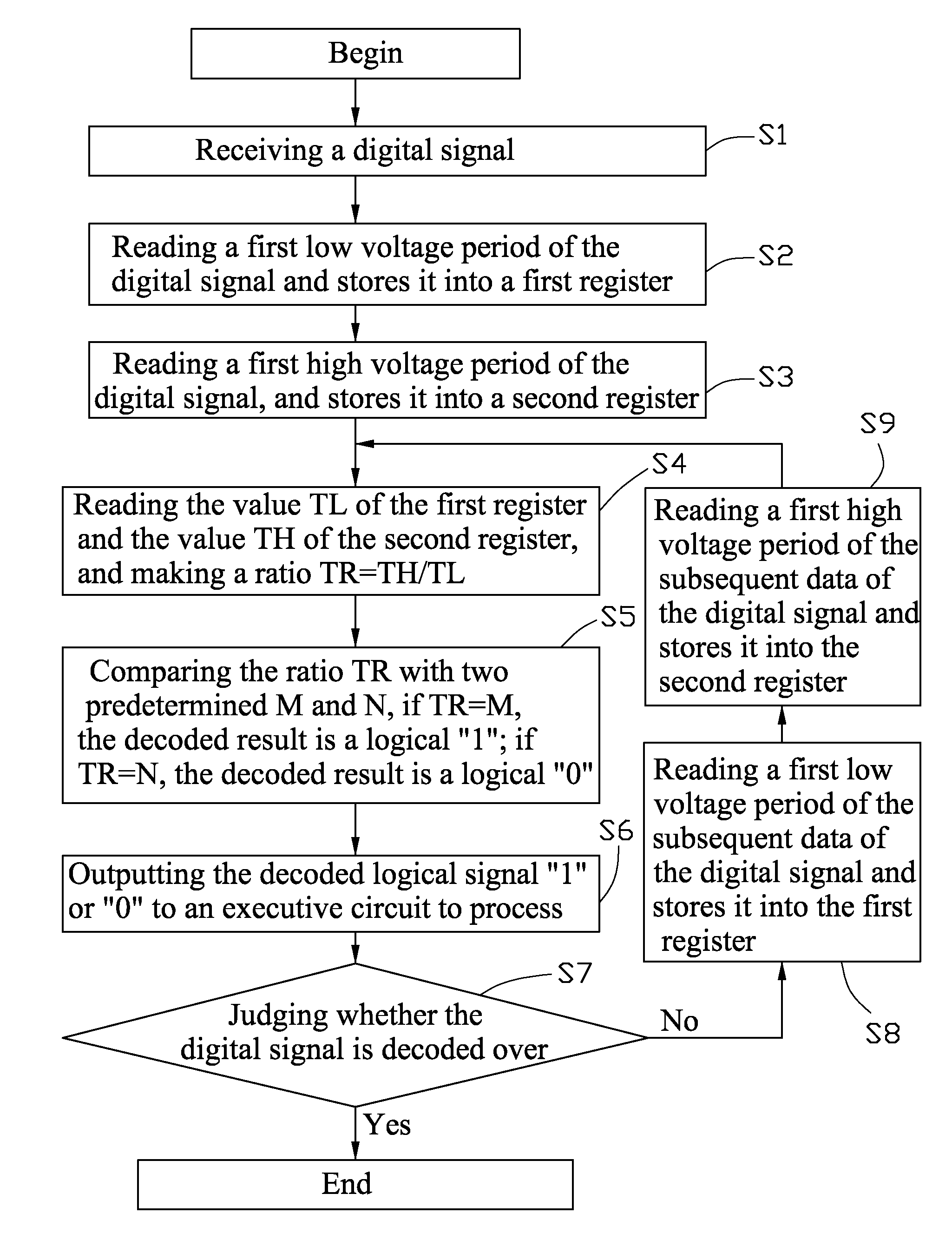
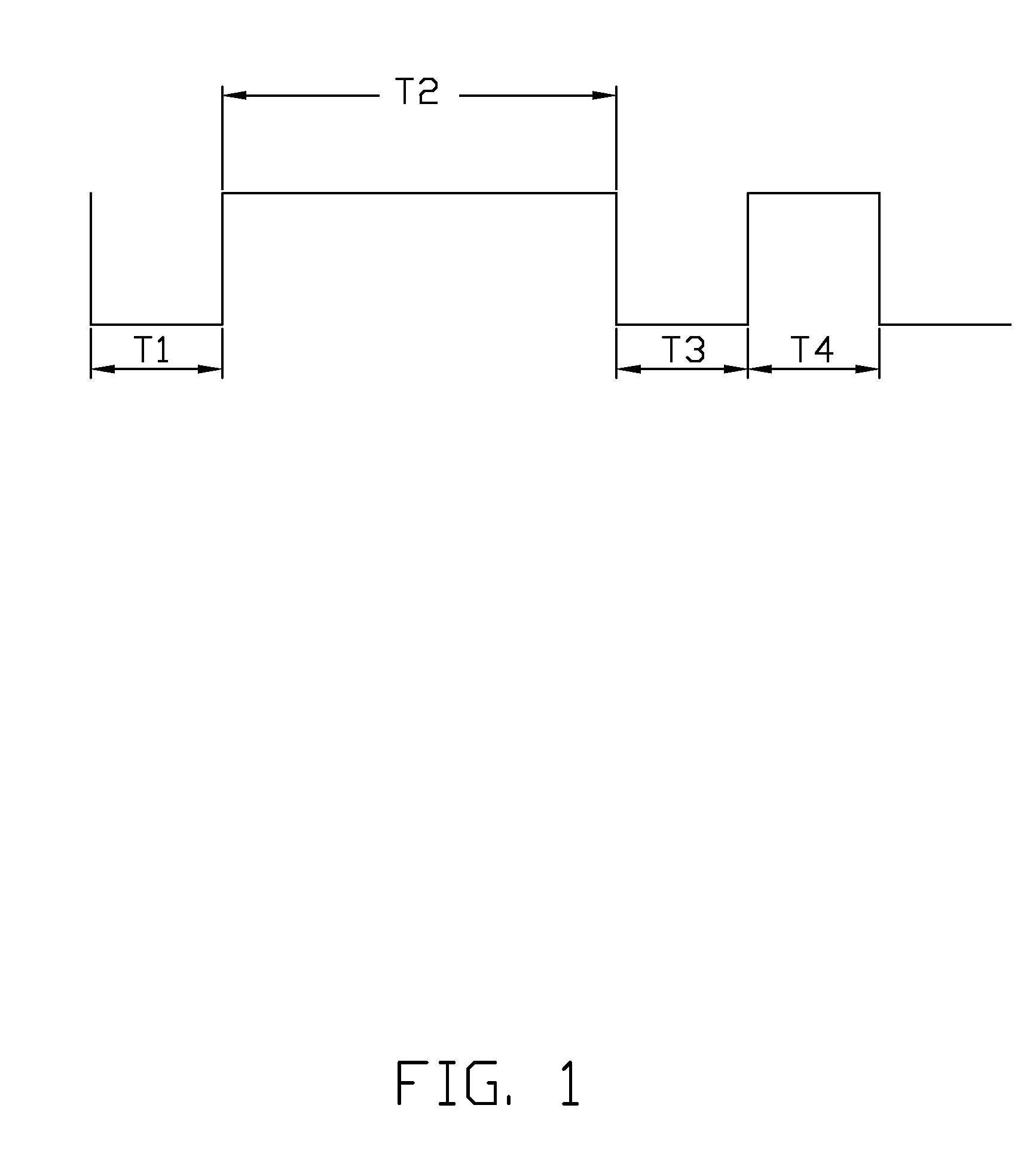
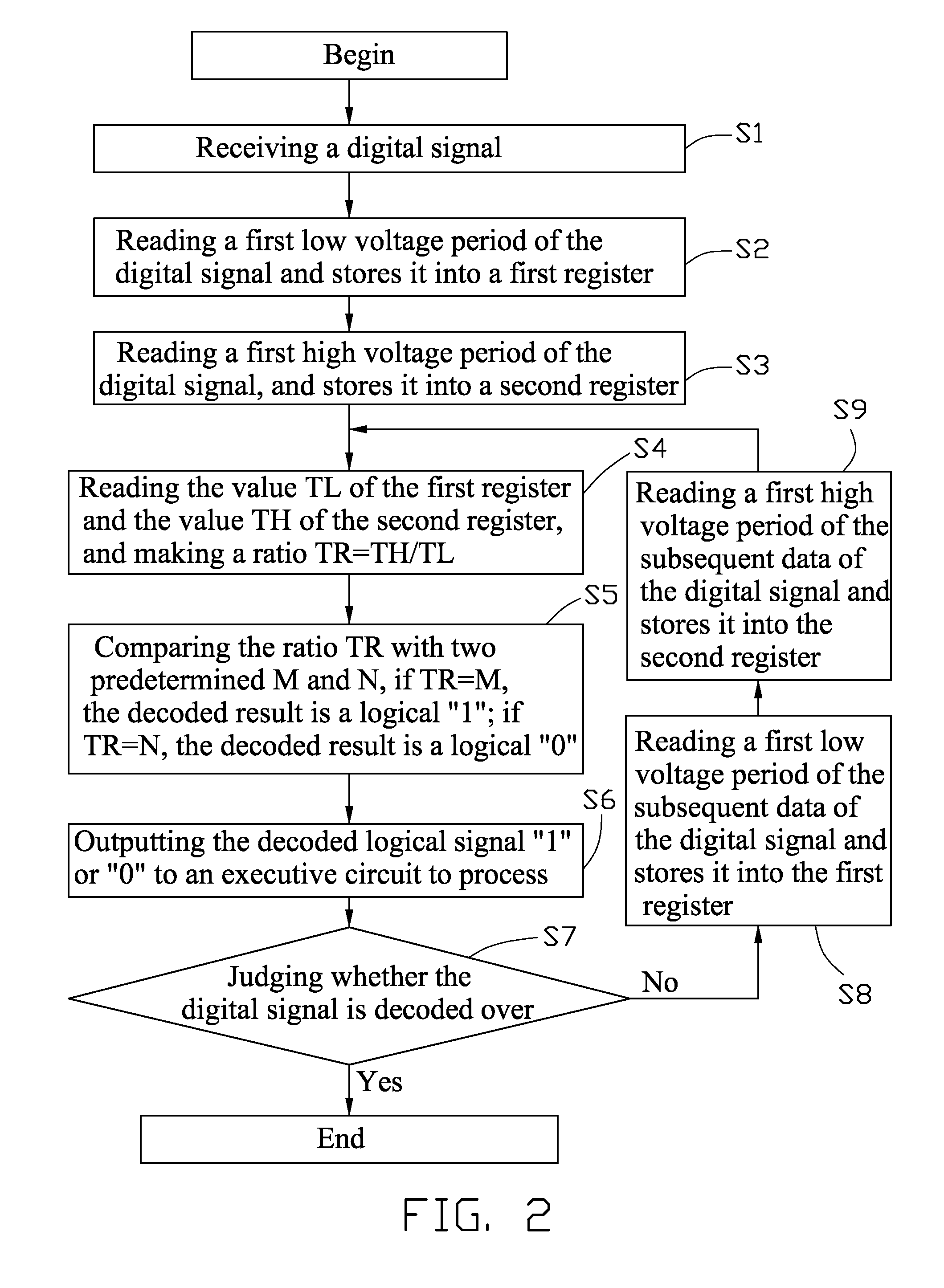
[0009]An exemplary embodiment of a digital signal decoding method to decode a digital signal as shown in FIG. 1 is illustrated. The digital signal may correspond to a logical “1” and a logical “0” following a semi-period of high and low voltage levels respectively. Furthermore, the digital signal may be encoded such that the logical “1” is formed as a semi-period low voltage followed by an M multiple of the semi-period high voltage (See T1 and T2 period in FIG. 1). Accordingly, the logical “0” is formed as a semi-period low voltage followed by an N multiple of semi-period high voltage (See T3 and T4 period in FIG. 1). The values M and N are predeterminedly different and are saved in a micro control unit (MCU). The predetermined values M and N each are not less than one, and in this embodiment, M=3, and N=1, namely T2 / T1=M=3, and T4 / T3=N=1. However, it may be understood that these values are exemplary and may differ depending on the embodiment.

[0010]The digital signal decoding method...


PUM


Abstract

A computer-implemented method to decode a digital signal includes following steps. A micro control unit (MCU) receives a digital signal. The MCU reads a low voltage period of the digital signal and stores a time duration of the low voltage period into a first register as a value TL. The MCU reads next high voltage period of the digital signal and stores a time duration of the high voltage period into a second register as a value TH. The MCU reads the value TL of the first register and the value TH of the second register, and computes a ratio TR=TH / TL. The MCU compares the ratio TR with two predetermined values M and N, if TR=M, the decoded result is a logical “1.” If TR=N, the decoded result is a logical “0.”

Description

BACKGROUND[0001]1. Field of the Disclosure[0002]The present disclosure relates to decoding methods, and particularly to a decoding method to decode a digital signal.[0003]2. Description of Related Art[0004]Referring to FIG. 3, two coordinate digital signals to be decoded by a typical digital signal decoding method is shown. According to this typical digital signal decoding method, after a semi-period (such as 0.56 ms in one example) low voltage, the digital signal reaches a rising edge, a voltage of a time point (such as 0.84 ms in one example) which is between a semi-period and a period after the rising edge is collected. If the collected voltage is at the high level (shown at a broken line of the upper schematic view), the digital signal is decoded as logical “1.” If the collected voltage is at the low level (shown at a broken line of the lower schematic view), the digital signal is decoded as logical “0.” However, if the frequency of the digital signal is unstable, the decoded lo...

Claims


Application Information

Patent Timeline
Patent Type & Authority Applications(United States)
IPC IPC(8): H03M7/04
CPCH03M5/08
Inventor SANG, SHENG-JIEDAI, LIANG-YAN
Owner HONG FU JIN PRECISION IND (SHENZHEN) CO LTD
Features
  • R&D
  • Intellectual Property
  • Life Sciences
  • Materials
  • Tech Scout
  • Unparalleled Data Quality
  • Higher Quality Content
  • 60% Fewer Hallucinations
Learn More