Actuator System Using Multiple Piezoelectric Actuators

Active Publication Date: 2010-02-04
ASML HLDG NV
View PDF4 Cites 31 Cited by
  • Summary
  • Abstract
  • Description
  • Claims
  • Application Information

AI Technical Summary

Benefits of technology

[0009]Therefore, what is needed is a system that accurately and reliably positions one or more optical elements within an optical device, while maintaining rel

Problems solved by technology

However, the accuracy with which a lens element can be positioned in such assemblies is degraded by the friction, stiction, and low or variable stiffness that are characteristic of existing slide assemblies.
Further, such friction, stiction, and low or variable stiffness affects even high-quality slides that employ low-friction materials, ball or roller bearings, or fluid bearings.
Similar deficiencies are present in existing mechanical actuators that are coupled to

Method used


Image

  • Actuator System Using Multiple Piezoelectric Actuators
  • Actuator System Using Multiple Piezoelectric Actuators
  • Actuator System Using Multiple Piezoelectric Actuators

Examples


Embodiment Construction

[0024]This specification discloses one or more embodiments that incorporate the features of this invention. The disclosed embodiment(s) merely exemplify the invention.

[0025]The scope of the invention is not limited to the disclosed embodiment(s). The invention is defined by the claims appended hereto.

[0026]The embodiment(s) described, and references in the specification to “one embodiment”, “an embodiment”, “an example embodiment”, etc., indicate that the embodiment(s) described may include a particular feature, structure, or characteristic, but every embodiment may not necessarily include the particular feature, structure, or characteristic. Moreover, such phrases are not necessarily referring to the same embodiment. Further, when a particular feature, structure, or characteristic is described in connection with an embodiment, it is understood that it is within the knowledge of one skilled in the art to effect such feature, structure, or characteristic in connection with other embo...


PUM


Abstract

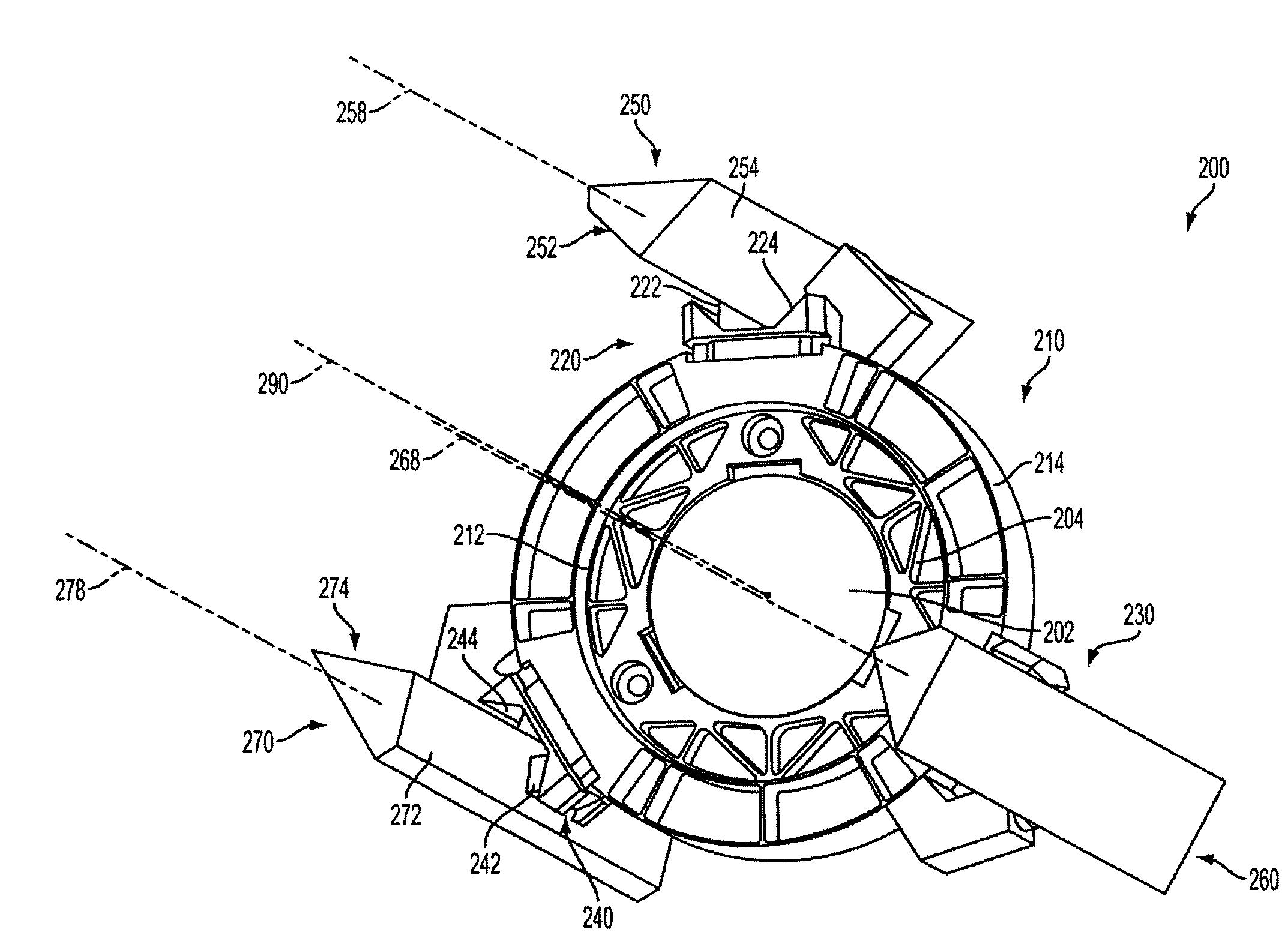
A positioning system adjusts a position of an optical element within an optical device, such as a variable-zoom lens system. A frame supports the optical element, and an elongated surface of each of one or more elongated support structures supports the frame. The frame also supports one or more piezoelectric actuators that, respectively, engage one of the elongated support structures. A controller supplies a control signal to activate each of the one or more actuator modules. Upon activation, a piezoelectric element of each of the activated actuator modules applies a combination of a first force and a second force to an elongated surface of the respective elongated support structures to position the frame along the elongated surface. The combination of forces applied by the piezoelectric element advances the piezoelectric actuator module along the elongated support structure.

Description

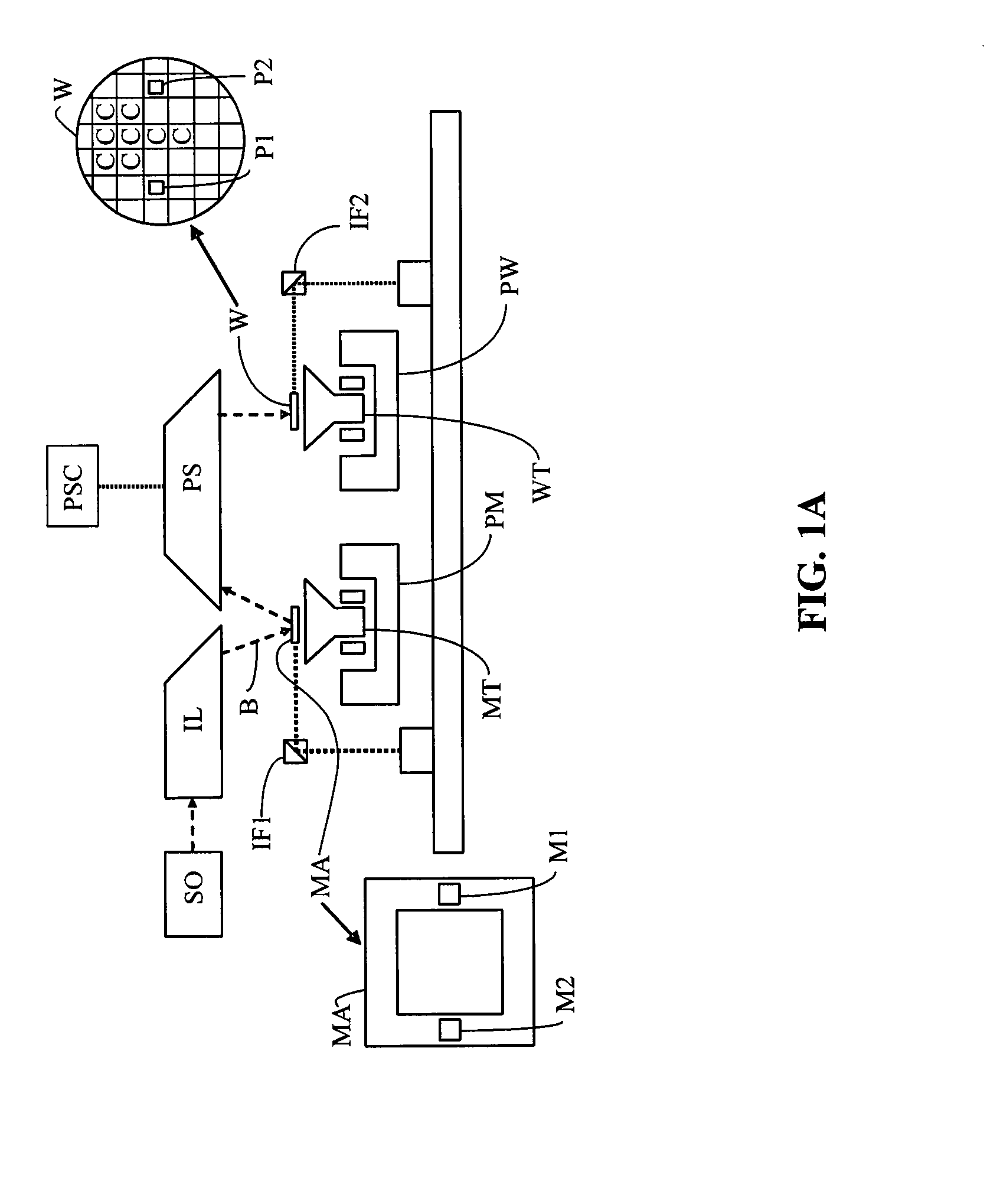
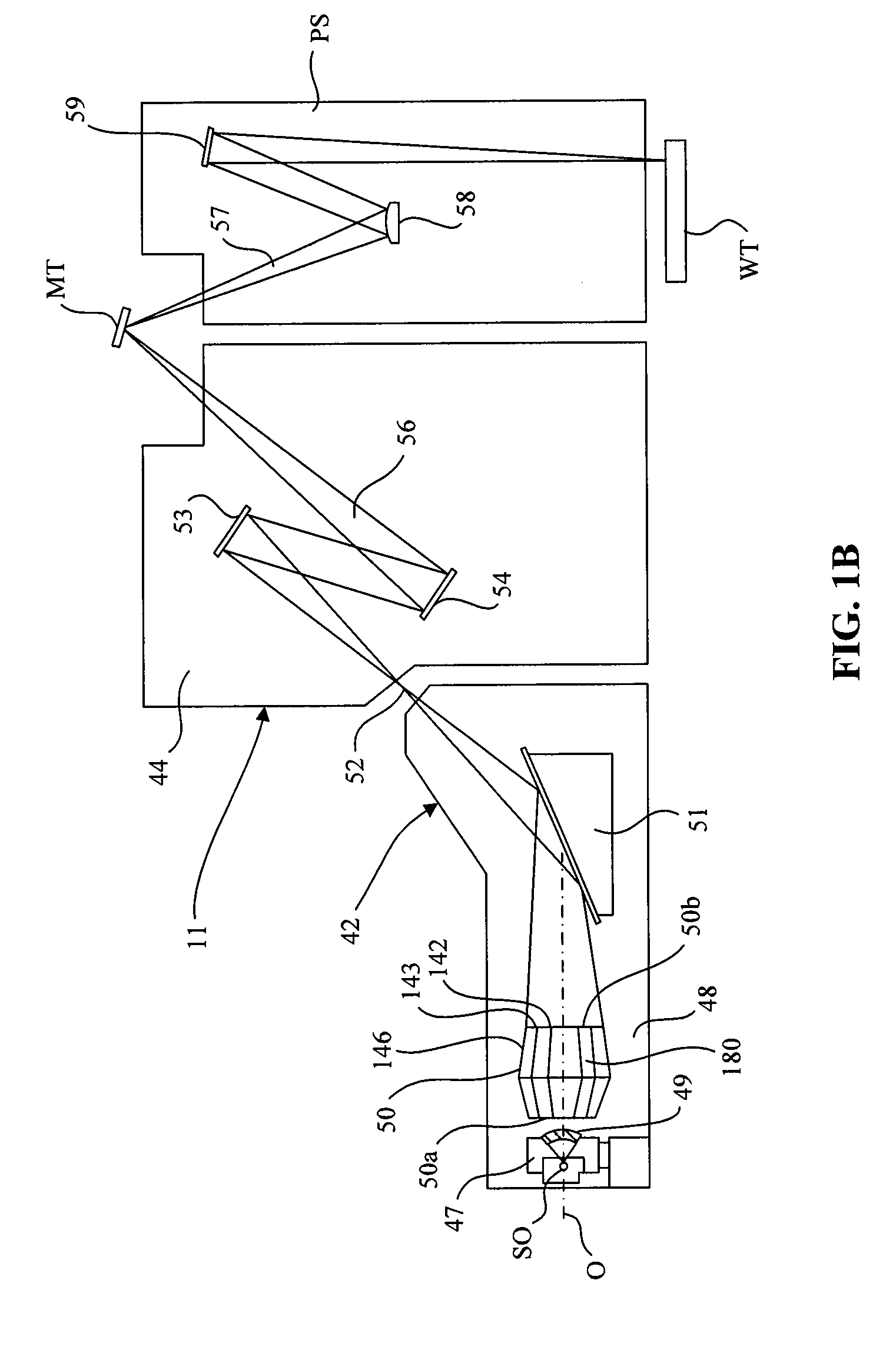
CROSS REFERENCE TO RELATED APPLICATIONS[0001]This application claims benefit under 35 U.S.C. §119(e) to U.S. Provisional Patent Application No. 61 / 084,772, filed Jul. 30, 2008, which is incorporated by reference herein in its entirety.BACKGROUND[0002]1. Field of the Invention[0003]The present invention relates to systems for positioning optical elements within a lithographic apparatus.[0004]2. Background Art[0005]A lithographic apparatus is a machine that applies a desired pattern onto a substrate or part of a substrate. A lithographic apparatus can be used, for example, in the manufacture of flat panel displays, integrated circuits (ICs) and other devices involving fine structures. In a conventional apparatus, light is directed to a patterning device, which can be referred to as a mask, a reticle, an array of individually programmable or controllable elements (maskless), or the like. The patterning device can be used to generate a circuit pattern corresponding to an individual laye...

Claims


Application Information

Patent Timeline
IPC IPC(8): G03B27/52G02B7/00G02B7/09
CPCG02B7/005G03F7/70825G03F7/70258
Inventor MEEHAN, MICHAEL F.SCIPIONE, FRED JOSEPH
Owner ASML HLDG NV
Why Eureka
Try Eureka