Image reading device and image forming apparatus

a reading device and image technology, applied in the direction of digital output to print units, instruments, television systems, etc., can solve the problems of undeired radiation (emi), image signal variation according, and inability to deal with variation

Active Publication Date: 2010-02-04
RICOH KK
View PDF10 Cites 52 Cited by
  • Summary
  • Abstract
  • Description
  • Claims
  • Application Information

AI Technical Summary

Benefits of technology

[0013]It is an object of the present invention to at least

Problems solved by technology

Speeding up of image reading devices has disadvantageously led to generation of undesired radiation (EMI).
In the conventional technology, however, because the frequency-modulated clock is used in the CCD4 and the AFE 5, there is a problem that the image signal varies according to a modulation period of the SSCG 2 (see FIG. 38).
Co

Method used


Image

  • Image reading device and image forming apparatus
  • Image reading device and image forming apparatus
  • Image reading device and image forming apparatus

Examples


Embodiment Construction

[0056]Exemplary embodiments of the present invention are explained in detail below with reference to the accompanying drawings. The same reference numerals are assigned to those equivalent to the components in the conventional example, and explanation thereof is omitted.

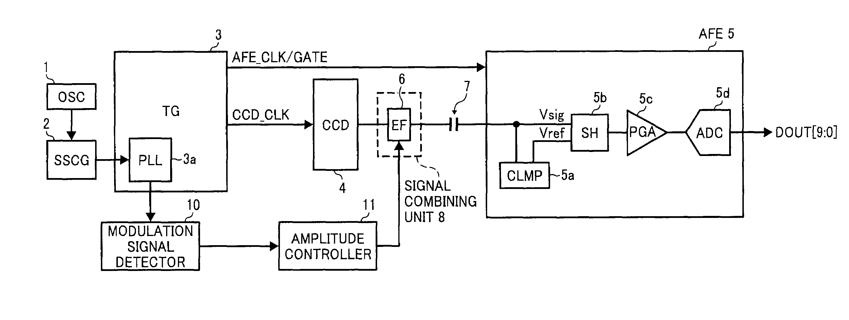
[0057]FIG. 1 is a diagram for explaining the concept of the present invention.

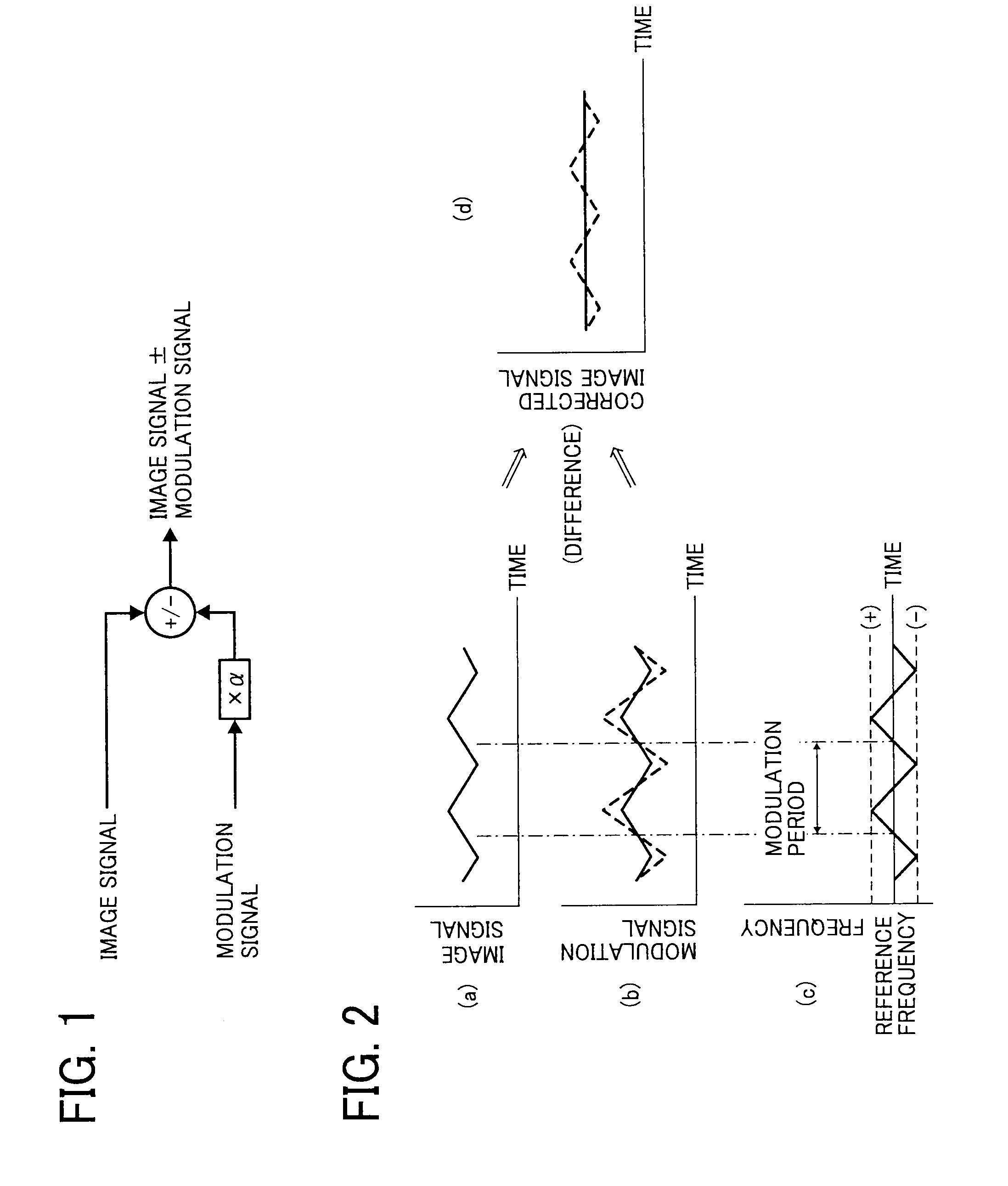
[0058]In order to correct the variation of an image signal depending on the modulation profile of the SSCG 2, in the present invention, a signal indicating a modulation profile (hereinafter, “modulation signal”) of the SSCG 2 is detected, and a signal whose amplitude is varied (α times) so as to be equivalent to a variation level of the image signal is superimposed on the image signal. FIG. 2 represents states of waveforms (a) to (d) when a difference between the image signal and the modulation signal is used to correct the variation. In an embodiment of the present invention, an amplitude of the modulation signal is caused to coincide with...


PUM


Abstract

An image reading device includes a charge-coupled device that generates and outputs an image signal, a timing generator that outputs a frequency-modulated clock, a modulation signal detector that detects a modulation signal being a signal corresponding to a change in frequency of the clock, an amplitude controller that controls an amplitude of the modulation signal, and a signal combining unit that superimposes the modulation signal after the amplitude is controlled on the image signal.

Description

CROSS-REFERENCE TO RELATED APPLICATIONS[0001]The present application claims priority to and incorporates by reference the entire contents of Japanese Patent Application No. 2008-195134 filed in Japan on Jul. 29, 2008 and Japanese Patent Application No. 2009-094349 filed in Japan on Apr. 8, 2009.BACKGROUND OF THE INVENTION[0002]1. Field of the Invention[0003]The present invention relates to image reading devices that optically read an image of an original. The present invention relates more particularly to an image reading device that can control a variation in an image level.[0004]2. Description of the Related Art[0005]In association with higher image quality and higher speed required of image forming apparatuses such as digital copiers, higher pixel density and higher speed upon image reading are also required of image reading devices provided in the image forming apparatuses. Digital copiers, facsimiles, and digital multifunction products are the examples of such image forming app...

Claims


Application Information

Patent Timeline
IPC IPC(8): G06F15/00H04N1/04G06T1/00H04N1/028H04N1/19
CPCH04N5/3765H04N5/3577H04N25/617H04N25/745
Inventor NAKAZAWA, MASAMOTO
Owner RICOH KK
Why Eureka
Try Eureka