Lens assembly

Active Publication Date: 2010-02-04
OM DIGITAL SOLUTIONS CORP
View PDF0 Cites 18 Cited by
  • Summary
  • Abstract
  • Description
  • Claims
  • Application Information

AI Technical Summary

Benefits of technology

[0032]The lens, disposed at the aperture on the subject side of the lens frame, is preferably fixed by means of caulking by heat or mechanical deformation of the lens frame, so that the specific members are not necessary for fixing lenses and the structure can be simplified.
[0033]Additionally, the sealing member is provided between the lens disposed at the aperture on the subject side and the lens frame for preventing the introduction of dust and improving waterproof effect, so that stable image acquisition can be realized.
[0034]Moreover, by providing the equi-diameter inner circumference faces for arranging the lenses with diameters being progressively smaller toward the diaphragm wall at the inner periphery surface of the lens frame, wrong assembly of the lens can be avoided and the good product quality can be stably maintained.
[0035]Furthermore, by disposing the elastic member provided with a plurality of arms, the size of lens assembly can be reduced (i.e., the distance between the first lens and an imaging element can be shortened).
[0036]The stopper can be provided on the inner face of the diaphragm wall such that not an edge of a through hole in the diaphragm wall but the stopper contacts the lens placed on the image side when an external vibration is inputted, so that generation

Problems solved by technology

Moreover, since flanges are formed on the lens, complicated lens processing is necessitated and thus the cost will grow.
Three locking parts are formed on the lens frame, for example, whereby it is difficult to gain sufficient support strength.
The conventional lens assembly as in JP 7-10710 U may not be assembled efficiently and accurately because the lens assembly has a large number of parts and the structure thereof is inevitably complicated.
As a result, when inserting each lens to the lens frame, the lens may fall over or inserted with its optical axis being tilt with respect

Method used


Image

  • Lens assembly
  • Lens assembly
  • Lens assembly

Examples


Example

The First Embodiment

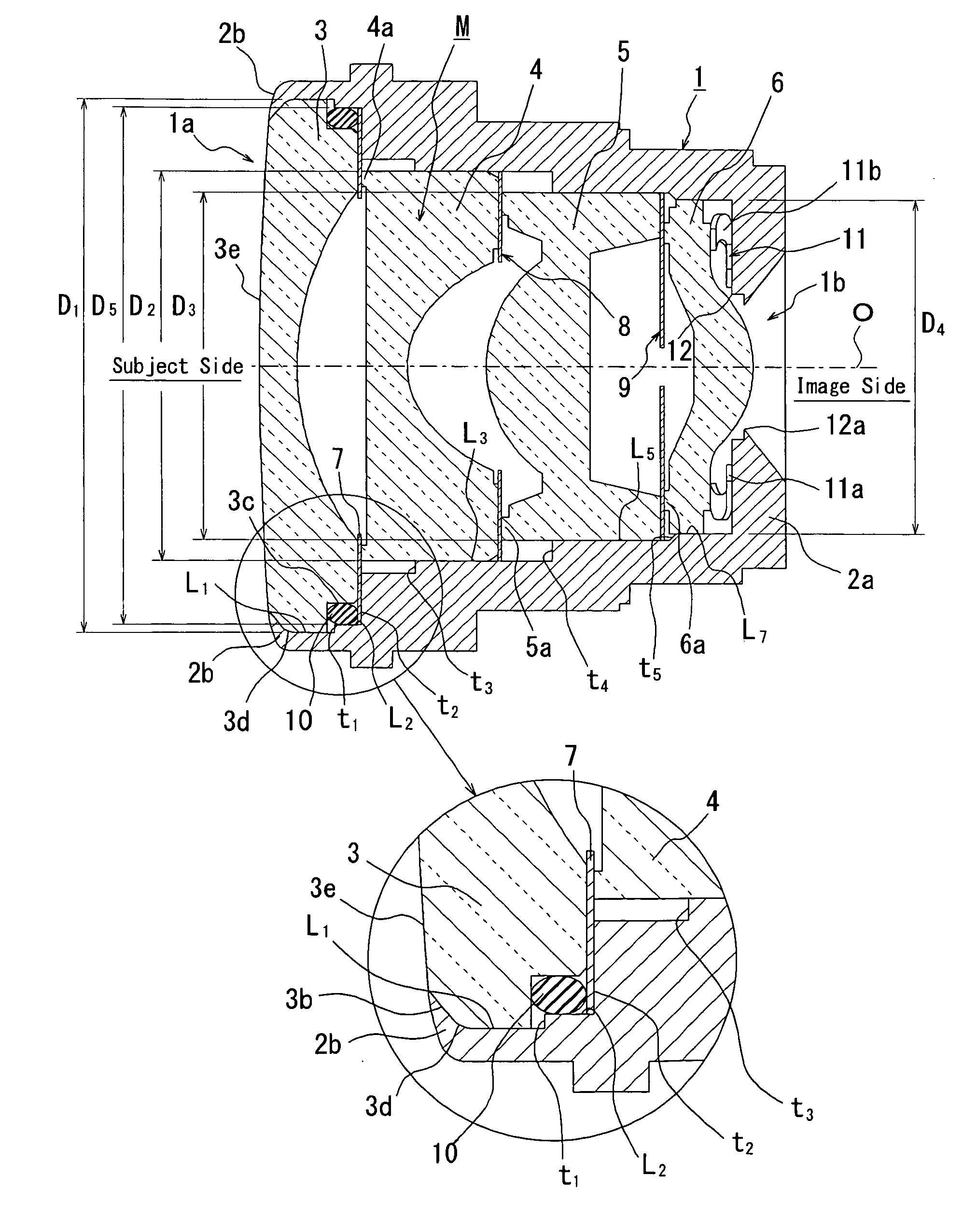
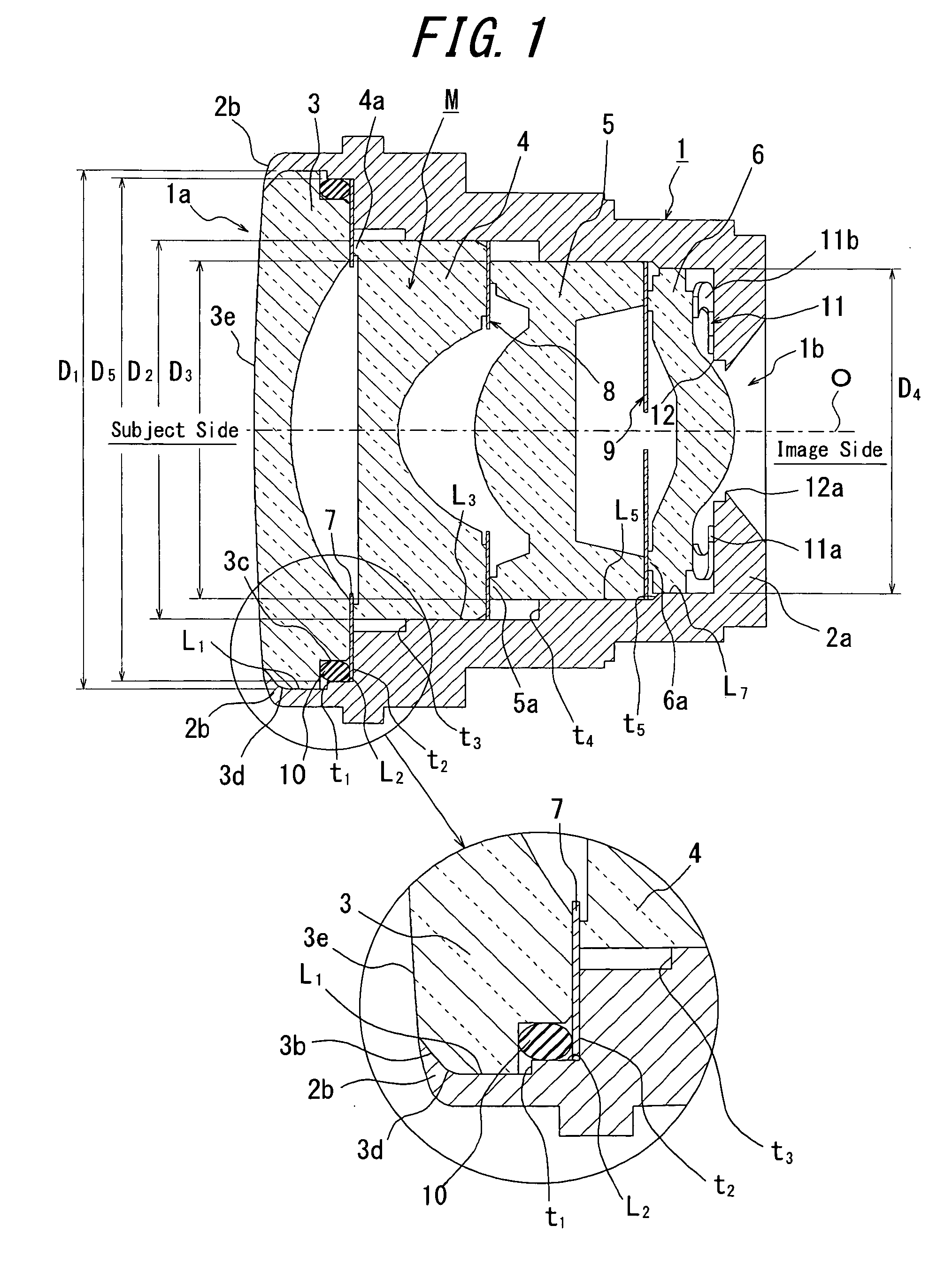
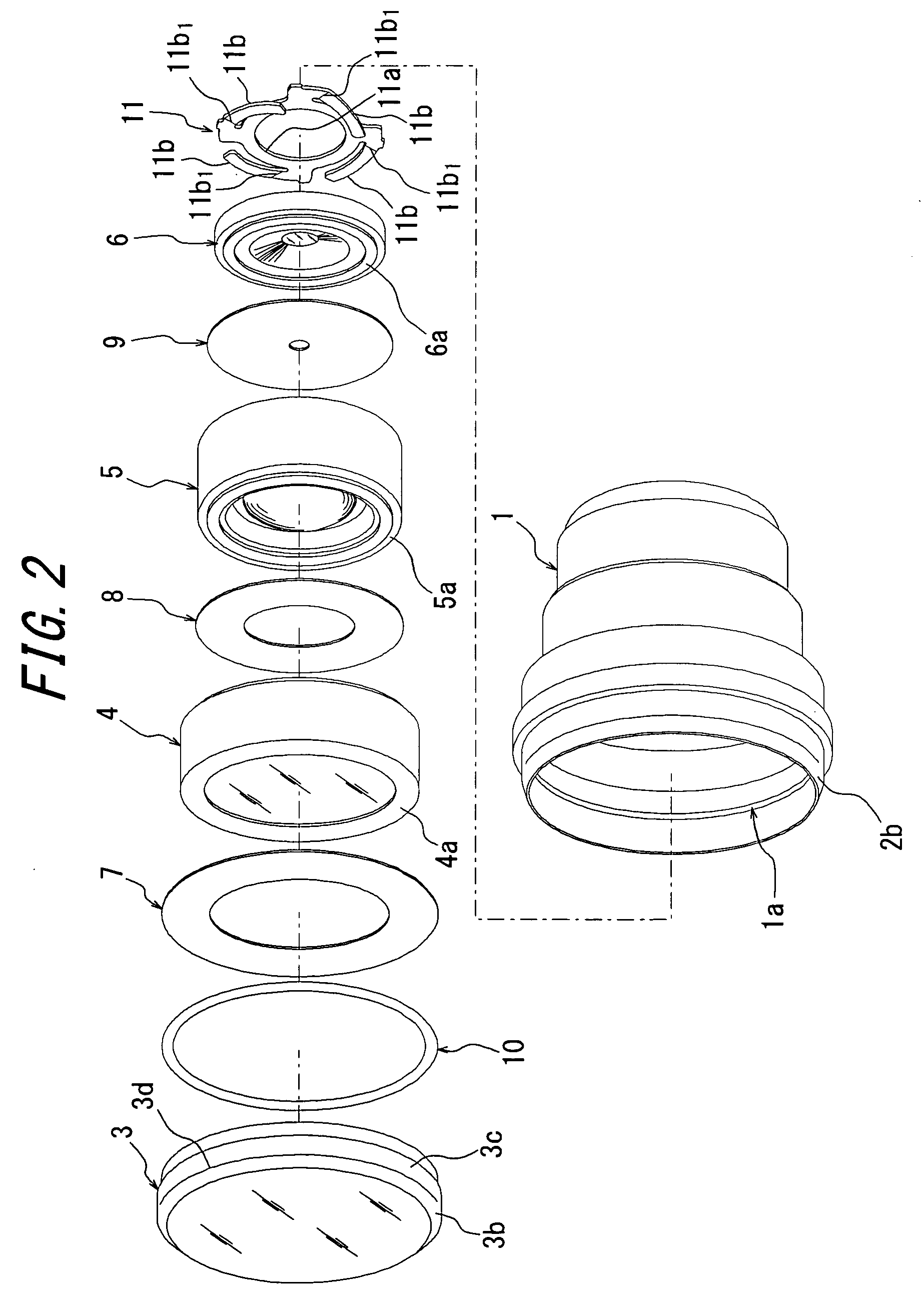
[0047]FIG. 1 is a cross sectional view schematically illustrating of a lens assembly according to an embodiment of the present invention and FIG. 2 is an exploded perspective view of FIG. 1.

[0048]As shown in FIGS. 1 and 2, the lens assembly of the present embodiment retains a lens group M comprising four lenses; the first lens 3, the second lens 4, the third lens 5, and the fourth lens 6, on a lens frame 1 along the optical axis O. In the present description, the side of the first lens 3 will be called the subject side (the left had side in the document sheet) and the side of the fourth lens 6 will be called the image side (the right hand side in the document sheet) hereinafter, for convenience. The subject side and the image side of each lens may respectively be called front side and back side.

[0049]The lens frame 1 comprises a circumferential wall of plastics or metal material, and has the subject side aperture 1a and the image side aperture 1b, each opens to b...

Example

The Second Embodiment

[0067]FIG. 5 is a cross sectional view schematically showing the lens assembly according to a second embodiment of the present invention, and FIG. 6 is an appearance perspective view showing an exploded state of the lens assembly as shown in FIG. 5

[0068]As shown in FIGS. 5 and 6, the lens assembly 1 according to the present embodiment is substantially the same as the lens assembly according to the first embodiment, except that the curvature of the lens face on the subject side of the first lens 3 is infinite, i.e. the lens face is flat, and the first lens 3 is supported at the chamfer 3b formed at the flat lens surface thereof by the entire circumference support 2b such that the entire circumference support 2b is continuous with the flat lens surface.

[0069]When the lens surface is flat, the chamfer is formed in the lens at an angle of approximately 45 degrees with respect to the flat lens surface, in a manner similar to the normal chamfering process, so as to su...

Example

The Third Embodiment

[0072]FIG. 7 is a cross sectional view schematically showing a structure of the lens assembly according to a third embodiment of the present invention, and FIG. 8 is an exploded perspective view thereof.

[0073]As shown in FIGS. 7 and 8, the lens assembly of the present embodiment comprises a lens group M, the lens frame 1, the first lens 3, the flare diaphragms 7 and 8, the aperture diaphragm 9, and the elastic member 11, which are configured similarly to those in the first embodiment.

[0074]The lens assembly of the present embodiment is basically the same as the lens assembly 1 of the first embodiment, except that the shapes of the outer circumferential surfaces of the second lens 4 and the third lens 5 and the shape of the inner peripheral portion of the lens frame 1 contacting thereto have bee modified.

[0075]Because of this, in the present embodiment, the second lens 4 is formed by the concave meniscus lens made of plastics, the equi-diameter outer circumferenti...


PUM


Abstract

A lens assembly comprises a lens group M and a lens frame 1 for retaining the lens group M. In this lens assembly, the lens frame 1 has an entire circumference support 2b for supporting the rim on the subject side, of each lens M, across the entire circumference thereof, and an end face support 2a for supporting the lens M on the image side. Each lens M comprises a chamfer 3b formed at a rim of a lens surface on the subject side across the entire circumference thereof, and the entire circumference support 2b supports the chamfer 3b such that the entire circumference support 2b is continuous with the lens surface at substantially the same radius of curvature with the lens surface. According to the present invention, there is provided a lens assembly which can reduce size and cost and has stable lens retaining ability.

Description

CROSS-REFERENCE TO APPLICATIONS[0001]The present application claims the priorities of Japanese Patent Application No. 2008-196629 filed on Jul. 30, 2008, Japanese Patent Application No. 2009-043286 filed on Feb. 26, 2009, and Japanese Patent Application No. 2009-045180 filed on Feb. 27, 2009, which are herein incorporated in their entirety for reference.FIELD OF THE INVENTION[0002]The present invention relates to a lens assembly adopted as a component of an on-board camera for back, right, and left views, and a monitoring camera, and the like, and simplifies the structure of the lens assembly for realizing an effective and accurate assembly of the lens assembly.BACKGROUND OF THE INVENTION[0003]A known structure for a conventional lens assembly comprises a receiving part formed on a lens frame, for positioning the lens along the optical axis, and a plurality of locking parts having elasticity and extending along the optical axis, formed at a plurality of places (e.g. three sites) of ...

Claims


Application Information

Patent Timeline
IPC IPC(8): G02B7/02G02B11/22
CPCG02B7/021
Inventor SODEYAMA, TOSHIYATANABE, YASUTAKAICHIKAWA, HIDEAKI
Owner OM DIGITAL SOLUTIONS CORP
Why Eureka
Try Eureka