Sound collection/reproduction method and device

a sound collection and sound technology, applied in the direction of pseudo-stereo systems, transducer details, electrical transducers, etc., can solve the problems of reducing the detection value of phase difference or the like, unable to accurately obtain the estimated unable to accurately estimate the position of received sound signals, so as to minimize the physical scale of the whole system

Active Publication Date: 2010-02-04
HAMADA
View PDF8 Cites 7 Cited by
  • Summary
  • Abstract
  • Description
  • Claims
  • Application Information

AI Technical Summary

Benefits of technology

[0021]The present invention constituted as described hereinabove affords the following effects. (1) Because microphones are arranged in closer proximity to one another than is the case with the existing systems, the physical scale of the whole system can be minimized. (2) Miniaturization is also possible from the perspective of data storage. (3), Since, information on the whole of the space sound field can be saved, compatibility with the existing sound field reproduction systems as well as the sound field reproduction systems that will be developed in the future is possible. (4) Cooperation with a virtualized (virtual sound source reproduction) system is straightforward and effective. (5) The sound collection status of each channel can be monitored by means of two-channels or headphones in a multichannel sound collection system which collects sound with an emphasis on sounds in a plurality of directions.

Problems solved by technology

However, the sound waves in the actual sound field are not limited to being planar waves, meaning that the estimated positions of the received sound signals cannot be accurately obtained.
In addition, although detecting the phase difference, time difference, and frequency difference of the sounds collected by a plurality of microphones and estimating the received sound signals in an arbitrary position based on these differences may also be considered, in this case, when the plurality of microphones are arranged in proximity to one another, the detected value for the phase difference or the like is diminished and erroneous effects are readily introduced, making an accurate estimate difficult.
Furthermore, generally speaking, in the field of sound collection or the editing field, the setting of the sound amount is in a suitable state and the setting conditions for the sound collection and editing cannot be improved and must always be confirmed.
However, it is difficult to prepare a bulky reproduction system of this kind in the sound collection field and monitoring has generally been performed using headphones or two-channel monitor speakers.
However, it has hitherto not been possible to confirm the status (the magnitude of the sound and the quality of each image fixed position) of each channel (the sound in each direction) of multichannel collected sound using conventional two-channel headphones or speakers.

Method used


Image

  • Sound collection/reproduction method and device
  • Sound collection/reproduction method and device
  • Sound collection/reproduction method and device

Examples


Embodiment Construction

[0022]An embodiment of the sound collection / reproduction system of the present invention will be described next in specific terms with reference to the drawings.

[0023](1) Example of Sound Collection Device:

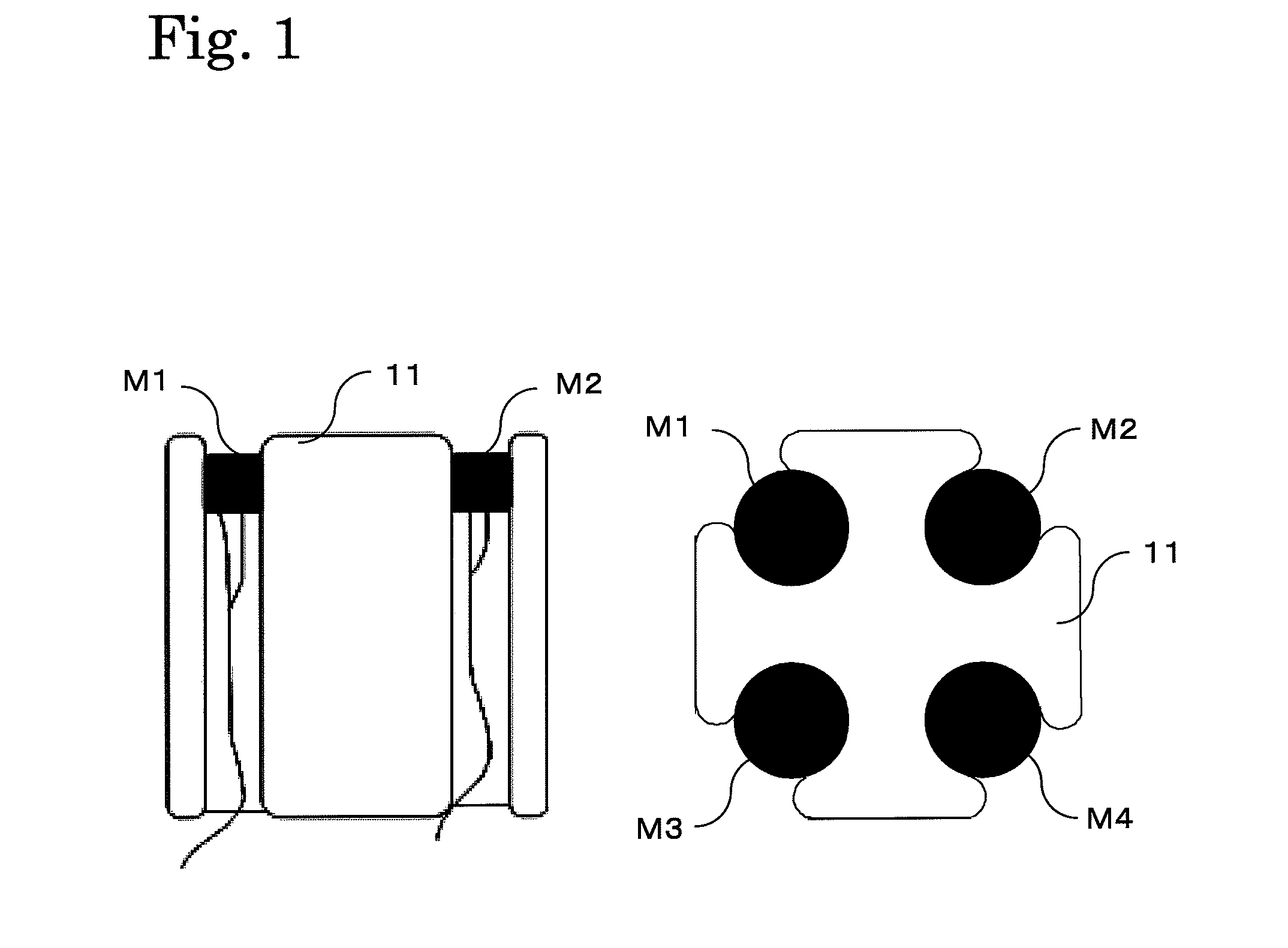
[0024]FIG. 1 shows an example of four microphones M1 to M4 which constitute a sound collection device 1 of this embodiment. Hence, these microphones M1 to M4 are housed in the holder 11 with the sound collection side oriented in the same direction.

[0025]The intervals between the respective microphones M1 to M4 are desirably intervals shorter than one quarter wavelength of the collected sound wave from the standpoint of the spatial sampling and the respective microphones M1 to M4 are disposed at a gap of about 10 mm in cases where the collected sound waves are in the audio bandwidth. However, the measurements are not restricted to those of this embodiment and may also range from about 100 mm to from 50 to 1 mm depending on the field of application. The number of channels from which...


PUM


Abstract

To provide a sound collection system using a plurality of microphones arranged in the proximity to one another and having an excellent directivity for an arbitrary position in the sound field space. A plurality of control points are set around a plurality of sound collecting microphones. A desired response function matrix A(ω) and a transfer function matrix C(ω) between the control points and the respective microphones are measured. A control filter H arranged in a digital signal processing unit (2) is connected to each of the microphones constituting the sound collection device (1). The control filters H are arranged for the number of output channels of a reproduction unit (4). An output of each of the control filters H is added for each channel and outputted to each channel of the reproduction unit (4). By specifying a microphone directivity upon sound collection at a control point, the control filters H are decided according to the measured desired response function matrix A(ω) and the transfer function matrix C(ω) of the specified control point.

Description

TECHNICAL FIELD[0001]The present invention relates to a sound collection / reproduction method and device capable of collecting sound with directivity in an arbitrary direction by using an array of microphones which are arranged in proximity to one another and of reproducing the collected sound in an arbitrary reproduction system with a different number of channels and a different reproduction device.BACKGROUND[0002]A microphone array device which employs a plurality of microphones as sound collection devices in a sound field is known. A technology which targets sound signals which are to be collected in targeted positions from among sound signals which are collected from microphones which are actually arranged instead of actually installing microphones and collecting sound in that manner has been proposed with the object of reducing the number of microphones in the microphone array device. The invention of Patent Document 1 is representative of this technology and estimates the sound...

Claims


Application Information

Patent Timeline
Patent Type & Authority Applications(United States)
IPC IPC(8): H04R3/00
CPCH04R5/027H04S5/005H04S3/002H04S2400/15H04R1/40H04R3/02H04S7/00
Inventor HAMADA, HAREOMURAYAMA, YOSHITAKAGOTO, AKIRA
Owner HAMADA
Why Eureka
Try Eureka