Drilling Machine

a drilling machine and gear shift technology, applied in boring/drilling machines, drilling/boring measurement devices, manufacturing tools, etc., can solve the problems of difficult shifting gears, difficult to carry the conventional drilling machine, complicated transmission, etc., and achieve the effect of convenient shifting between gears and carrying conveniently

Inactive Publication Date: 2010-02-04
SHUN BAO ENTERPRISE
View PDF7 Cites 10 Cited by
  • Summary
  • Abstract
  • Description
  • Claims
  • Application Information

AI Technical Summary

Benefits of technology

[0005]It is the primary objective of the present invention to provide a drill

Problems solved by technology

However, the transmission is complicated, bulky and heavy.
It is therefore difficult to carry the conventional drilling

Method used


Image

  • Drilling Machine
  • Drilling Machine
  • Drilling Machine

Examples


Embodiment Construction

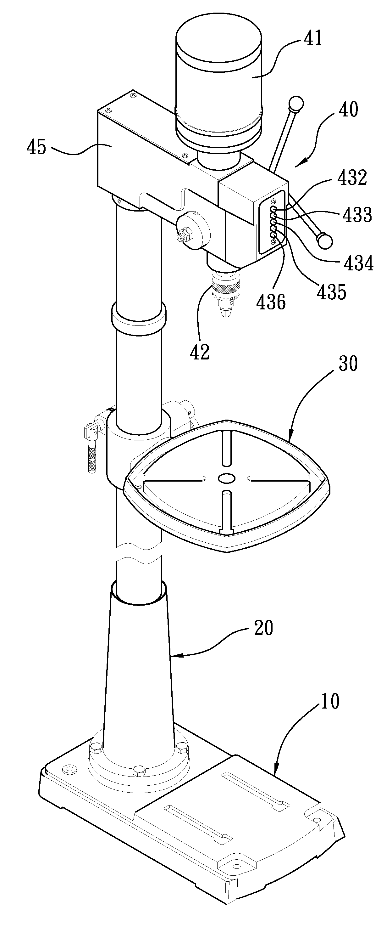
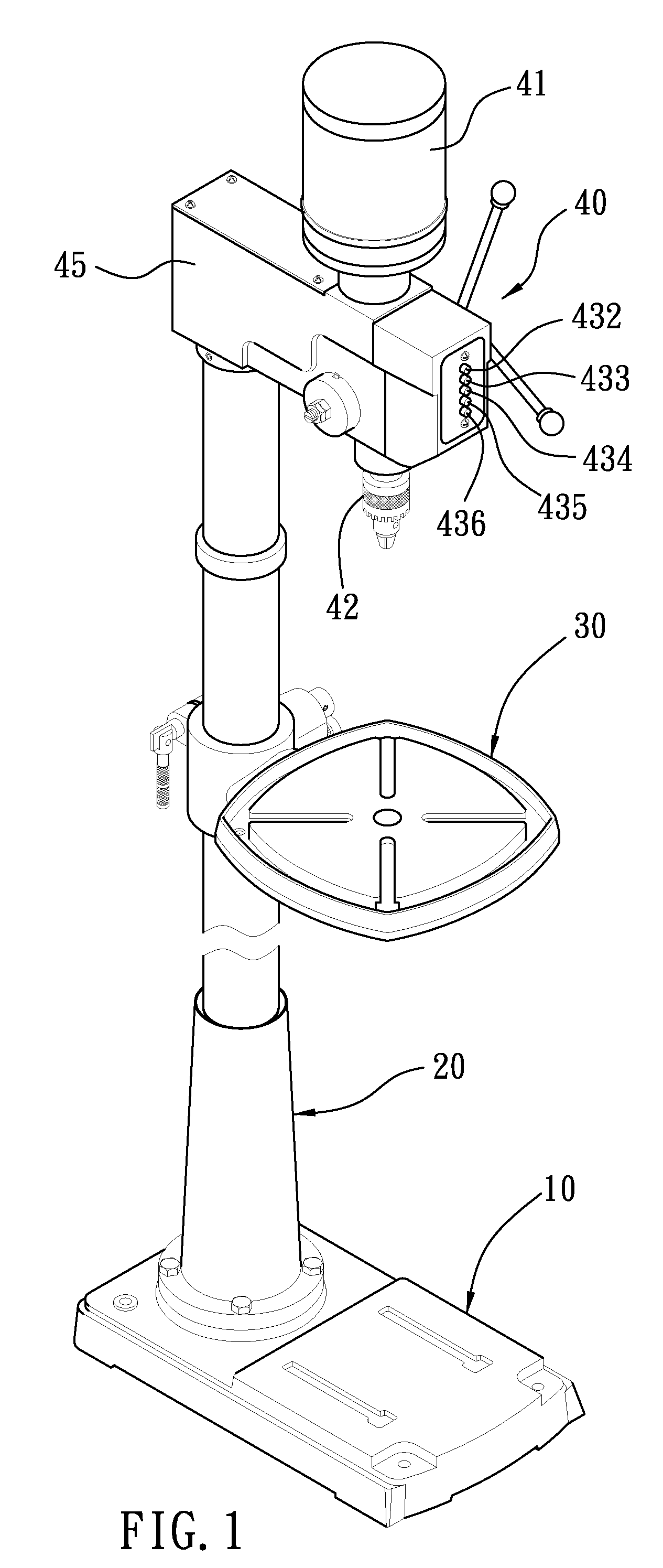
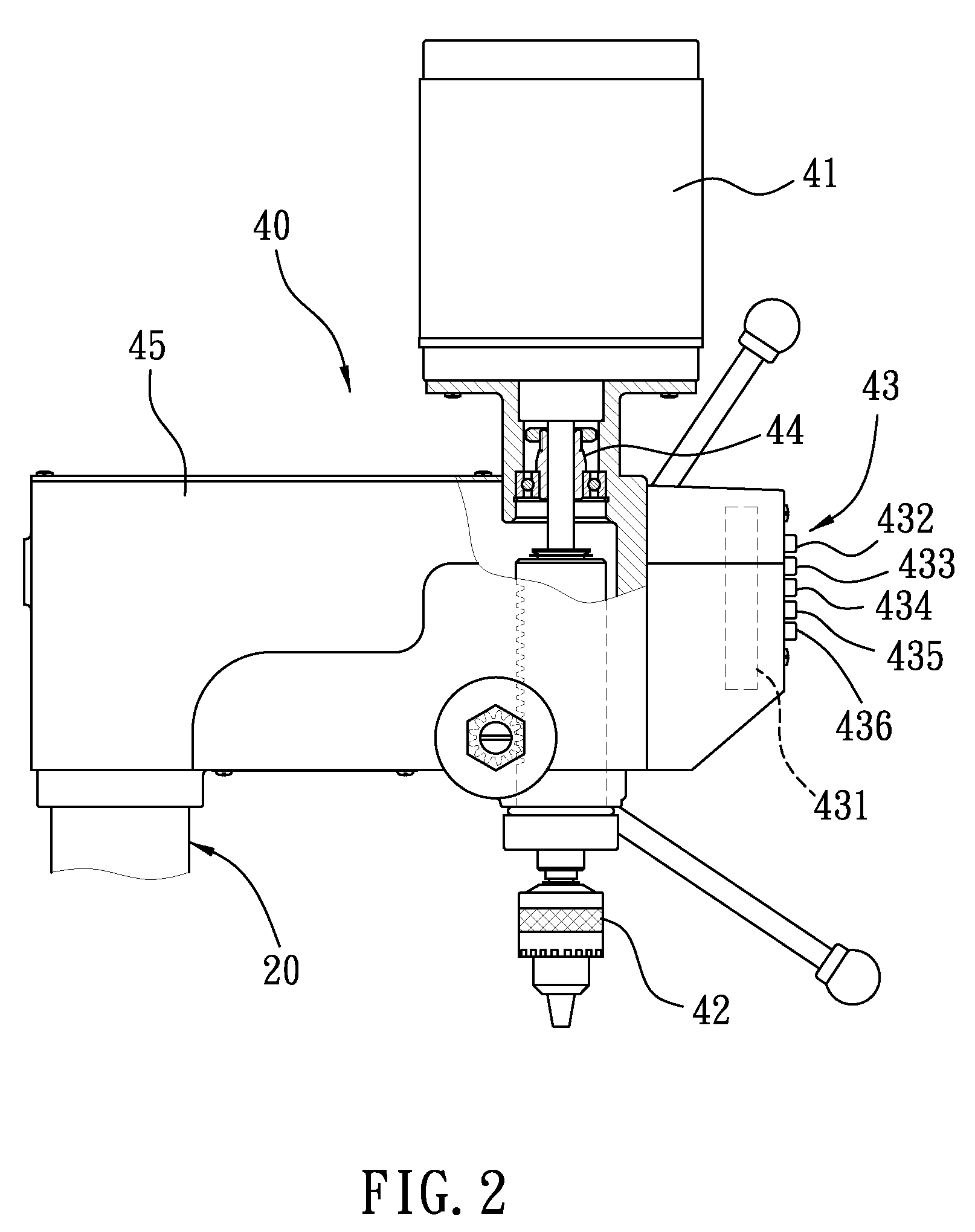
[0011]Referring to FIGS. 1 and 2, a drilling machine includes a base 10, a post 20, a worktable 30 and a drilling unit 40 according to the preferred embodiment of the present invention.

[0012]The base 10 is installed on a horizontal surface such as the ground or a floor. The post 20 is secured to the base 10. The base 10 and the post 20 are used to support the entire drilling machine.

[0013]The worktable 30 is movably connected to the post 20. A work piece can be supported on the worktable 30.

[0014]The drilling unit 40 includes a direct-current (ODCO) brushless motor 41, a drill 42, a transmission 43, a bearing set 44 and a shell 45. The shell 45 is secured to an upper end of the post 20. The DC brushless motor 41 is provided on the shell 45. The DC brushless motor 41 includes a mandrel connected to the drill 42 co-axially through the bearing set 44. The mandrel of the DC brushless motor 41 and the bearing set 44 are covered with the shell 45 so that the shell 45 protects the mandrel ...


PUM

PropertyMeasurementUnit
Transmissionaaaaaaaaaa

Abstract

A drilling machine includes a base located on a horizontal surface, a post provided on the base, a worktable movably connected to the post and a drilling unit provided on the post. The drilling unit includes a direct-current brushless motor, a drill and a transmission. The direct-current brushless motor is provided on the post. The drill is operatively connected to the direct-current brushless motor. The transmission includes a circuit board and gear-related buttons operable to instruct the circuit board to convert an alternating current into various direct currents to cause the motor and, therefore, the drill to rotate at various rotational rates.

Description

FIELD OF INVENTION[0001]The present invention relates to a drilling machine and, more particularly, to drilling machine that can be carried conveniently and shifted between gears easily.BACKGROUND OF INVENTION[0002]As disclosed in U.S. Pat. No. 5,769,575, a conventional drilling machine includes a drill, a motor and a transmission through which the motor drives the drill. The transmission includes a first conical pulley connected to the motor, a second conical pulley connected to the drill and a belt wound around the first and second conical pulleys. The first conical pulley is made with a stepped form including sections of different diameters. Similarly, the second conical pulley is made with a stepped form including sections of different diameters. The first and second conical pulleys and the belt are arranged so that the belt is wound around the largest section of the first conical pulley and the smallest section of the second conical pulley or a smaller section of the first coni...

Claims


Application Information

Patent Timeline
IPC IPC(8): B23B39/00
CPCY10T408/5626B23B39/00
Inventor YANG, TSAN-MINGYANG, TSAN-HSINLIN, SHU-SEN
Owner SHUN BAO ENTERPRISE
Why Eureka
Try Eureka