
Auto-disable device for syringes

Active Publication Date: 2010-02-04
ABU DHABI NAT IND PROJECTS
View PDF20 Cites 18 Cited by
  • Summary
  • Abstract
  • Description
  • Claims
  • Application Information

AI Technical Summary

Benefits of technology

[0005]Being external to the barrel of the syringe, the auto-disable device can be used with syringes of different sizes. There are therefore no practical limitations to the syringe barrel dimensions. The device can be conveniently attached to syringes that are intended for single use, to convert them into auto-disable syringes, provided that the outer luer cone of the syringe barrel is adjusted to permit locking of the device to the barrel. The device disables the syringe by means of the expulsion of liquid from the syringe in the course of doing an injection, without a further action to disable the syringe. Thus the term, “auto-disable.”
[0006]The auto-disable device, which includes the needle, can be assembled with the syringe at the factory and delivered as a unit, or, alternatively, the device can be provided separate from the syringe and be attached to it by a medical practitioner prior to use.

Problems solved by technology

Further, because of the requirement that the devices fit inside the barrel, there is a practical lower limit to the size of syringe in which such devices can be installed.

Method used


Image

  • Auto-disable device for syringes
  • Auto-disable device for syringes
  • Auto-disable device for syringes

Examples


Embodiment Construction

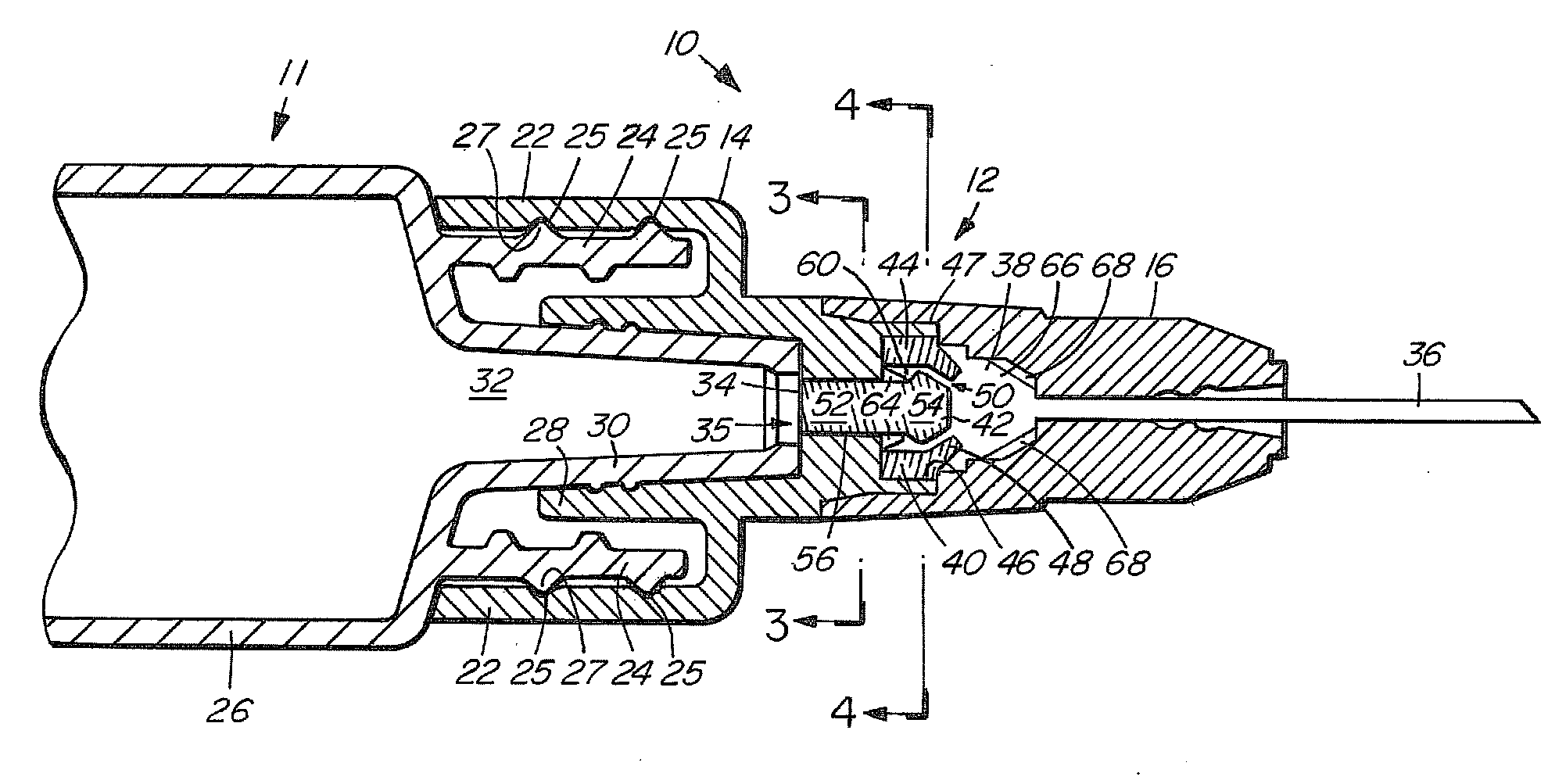
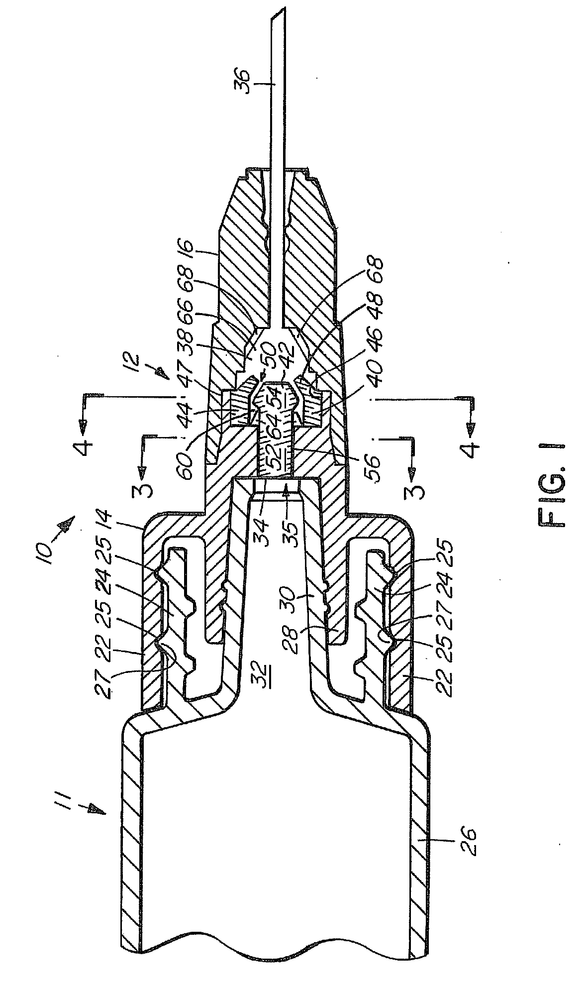
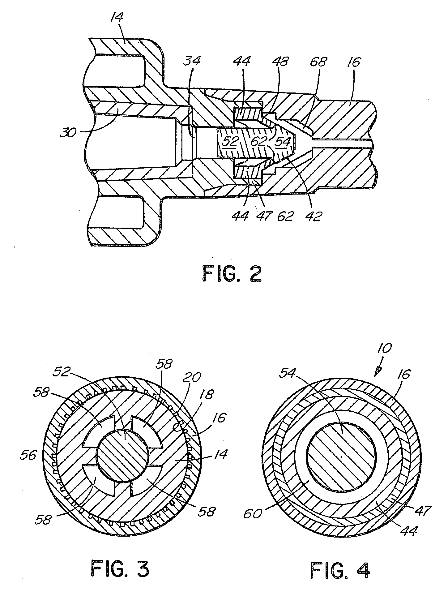
[0013]The auto-disable device 10 is shown in FIG. 1 attached to a sterile single use hypodermic syringe 11. The device 10 has an assembly 12 formed of a barrel adapter 14 and a needle hub 16. The barrel adapter and hub attach securely together by means of circumferentially-disposed ribs 18 on the barrel adapter which interfit tightly with mating grooves 20 on the needle hub. A hypodermic needle 36 is affixed to the distal end of the needle hub.

[0014]The barrel adapter 14 has an outer circumferential wall 22 for locking engagement with a luer lock cone 24 of the barrel 26 of the syringe. A number of circumferential grooves 25 on the inner surface of the wall 22 interfit with circumferential ridges 27 on the outer surface of the luer lock cone 24 of the barrel, providing a snap-on fit. The barrel adapter 14 has an inner circumferential wall 28 for mating engagement with the outlet cone 30 at the outlet end 32 of the barrel. The barrel adapter 14 has an inlet 34 at an inlet end 35 ther...


PUM


Abstract

An auto-disable device for use with a sterile single use hypodermic syringe has a barrel adapter configured to attach to the outlet end of the syringe barrel, external to the barrel. A needle hub holding a hypodermic needle is affixed to the barrel adapter, the barrel adapter and the needle hub forming an assembly having a cavity with a passage for the flow of liquid through the device. An elastically-deformable sealing ring and a moveable sealing member having a head and a shaft are positioned in the cavity. The sealing member is moveable within the cavity. The ring and moveable sealing member are configured to form a seal, after a single use of the syringe, against a flow of liquid into the syringe for refilling of the syringe.

Description

FIELD OF THE INVENTION[0001]The invention pertains to devices for preventing the reuse of sterile single use syringes.BACKGROUND OF THE INVENTION[0002]It is known to provide a hypodermic syringe with a device that prevents it from being used more than a single time. Such devices are typically installed in the syringe barrel between the piston and the outlet end of the barrel and prevent the syringe from being refilled. An example is shown in Meyer et al., U.S. Pat. No. 5,613,951. Since the devices are internal to the syringe barrel, either the barrel is sized and configured to fit a device of a specific diameter, or the devices are made in different sizes to fit the barrels of syringes of different sizes. Further, because of the requirement that the devices fit inside the barrel, there is a practical lower limit to the size of syringe in which such devices can be installed.SUMMARY OF THE INVENTION[0003]The invention provides an anti-reuse device for a syringe, the device being exter...

Claims


Application Information

Patent Timeline
IPC IPC(8): A61M5/00
CPCA61M5/348A61M2005/5053A61M5/504
Inventor KAKISH, AMER F.A.AL OMARI, OSAMA Y.T.
Owner ABU DHABI NAT IND PROJECTS
Learn More