
Thermally conductive module

a technology heat pipes, applied in indirect heat exchangers, heat exchange apparatus, lighting and heating apparatus, etc., can solve the problems of increasing the cost of complex manufacturing processes, increasing the cost of thermally conductive modules, and reducing the thermally conductive effect, so as to increase the thermally conductive area of heat pipes, increase thermally conductive performance, and weight reduction

Inactive Publication Date: 2010-02-11
HUANG SHIH WEI +1
View PDF12 Cites 9 Cited by
  • Summary
  • Abstract
  • Description
  • Claims
  • Application Information

AI Technical Summary

Benefits of technology

[0008]Therefore, in order to solve aforementioned problems, the invention is mainly to provide a thermally conductive module, whereby heat pipe, base seat and thermally conductive copper block are simultaneously attached to a surface of heating element, thus, effectively boosting the thermally conductive performance entirely.
[0009]Secondary, the invention is to provide a thermally conductive module, whereby a thermally conductive copper block is inset into a base seat, such that the thermally conductive copper seat is contacted tightly with the heat pipe, effectively increasing the thermally conductive area and entirely boosting the thermally conductive speed.
[0011]Fourthly, the invention is to provide a thermally conductive module, whereby a heat-releasing section is extended from a heated section of heat pipe and formed at one side of a base seat or is extended to two sides of the base seat, thus, effectively increasing the thermally conductive area of the heat pipe and entirely increasing the thermally conductive performance of the invention.
[0012]Finally, the invention is to provide a thermally conductive module, whereby a base seat is made by an aluminum extrusion, so its weight is lighter, effectively reducing the manufacturing cost entirely.

Problems solved by technology

However, the thermally conductive module according to prior arts still has following drawbacks in terms of practical use.
For example, sine the base seat is made of a copper material, its weight is heavier and it has a higher cost caused by complicated manufacturing process.
In addition, the only thermally conductive mechanism is constituted by attaching the base seat to the heating element, which is unable to effectively conduct the heat away from the heating element, because of a larger thermal resistance, so its thermally conductive effect is quite limited.

Method used


Image

  • Thermally conductive module
  • Thermally conductive module
  • Thermally conductive module

Examples


Embodiment Construction

[0019]In cooperation with attached drawings, the technical contents and detailed description of the present invention are described thereinafter according to a number of preferable embodiments, not used to limit its executing scope. Any equivalent variation and modification made according to appended claims is all covered by the claims claimed by the present invention.

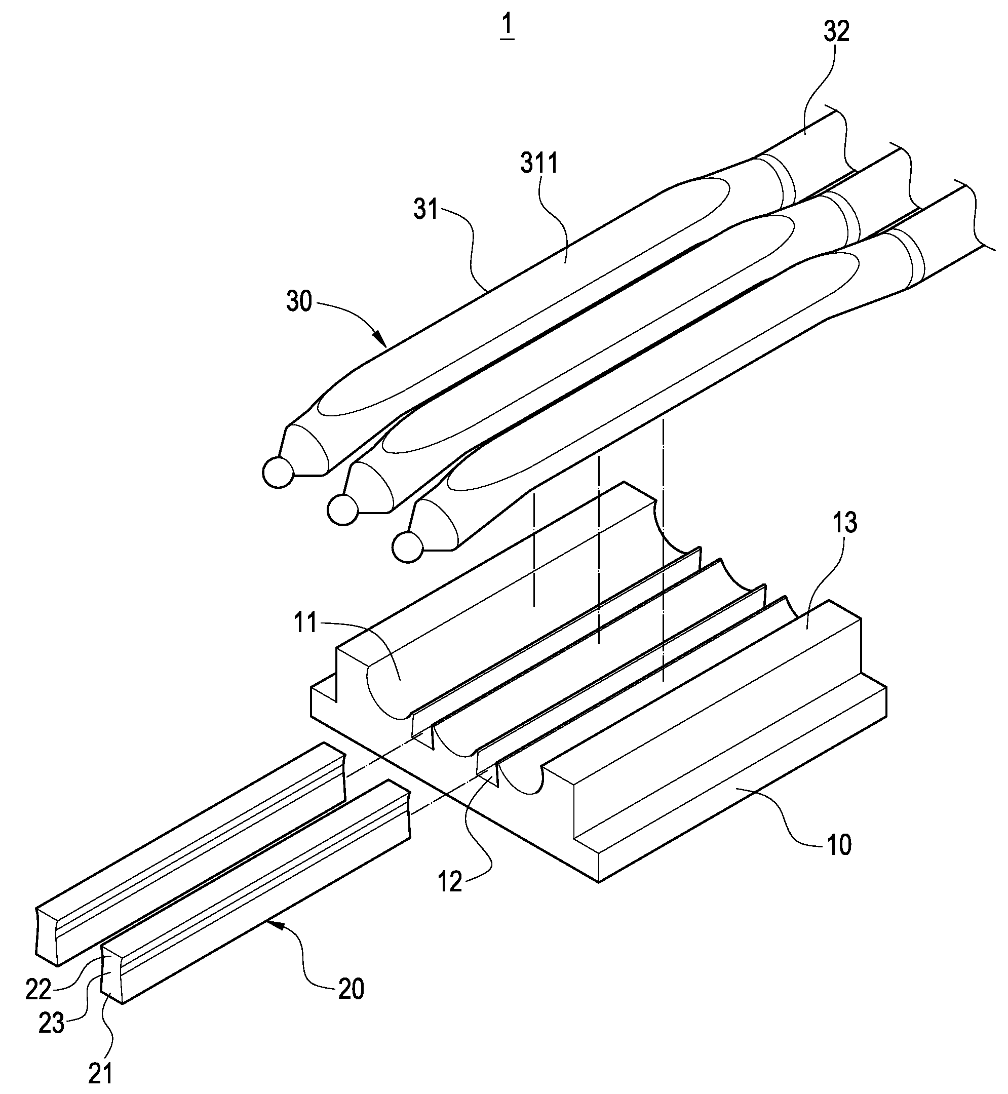
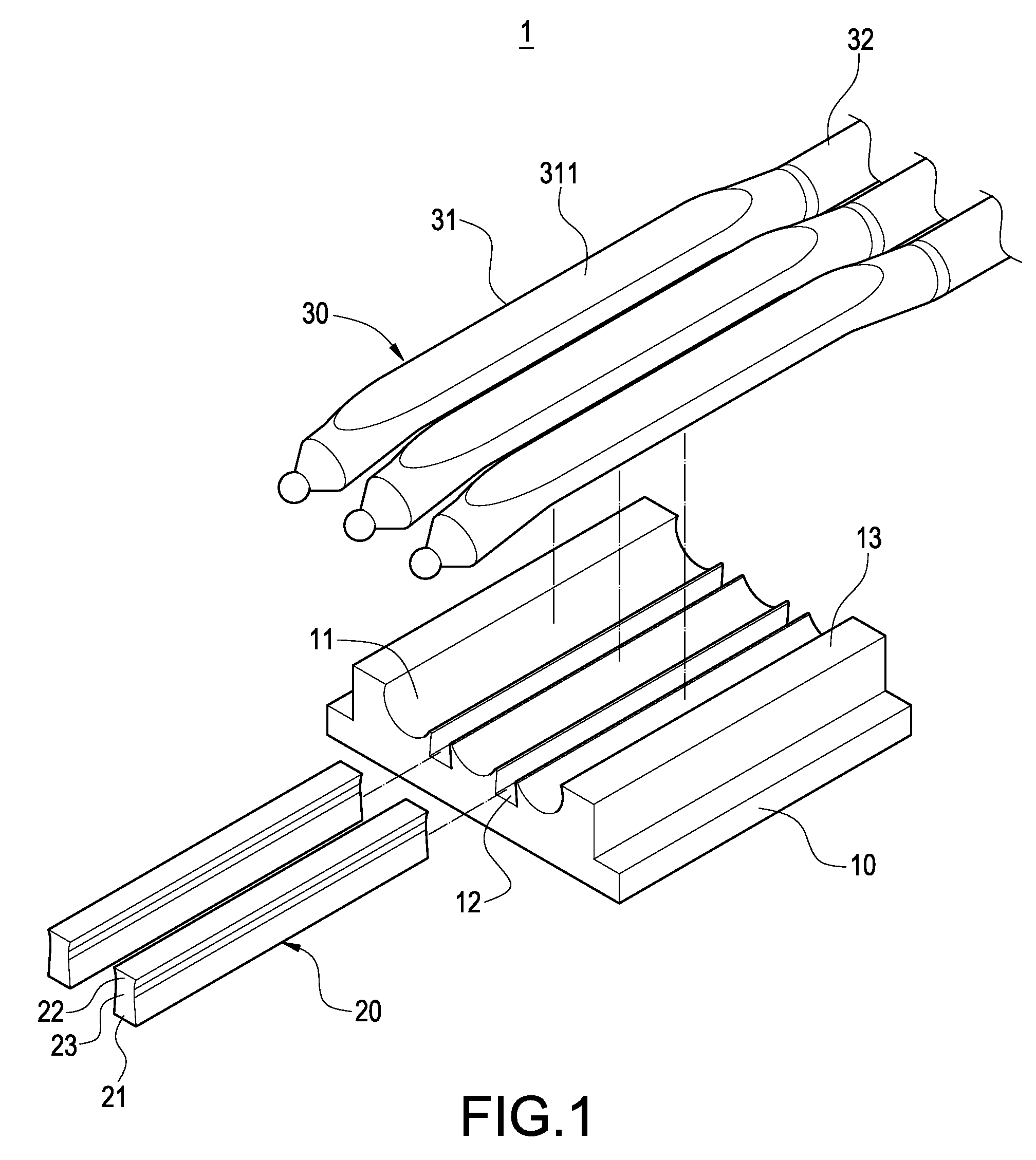
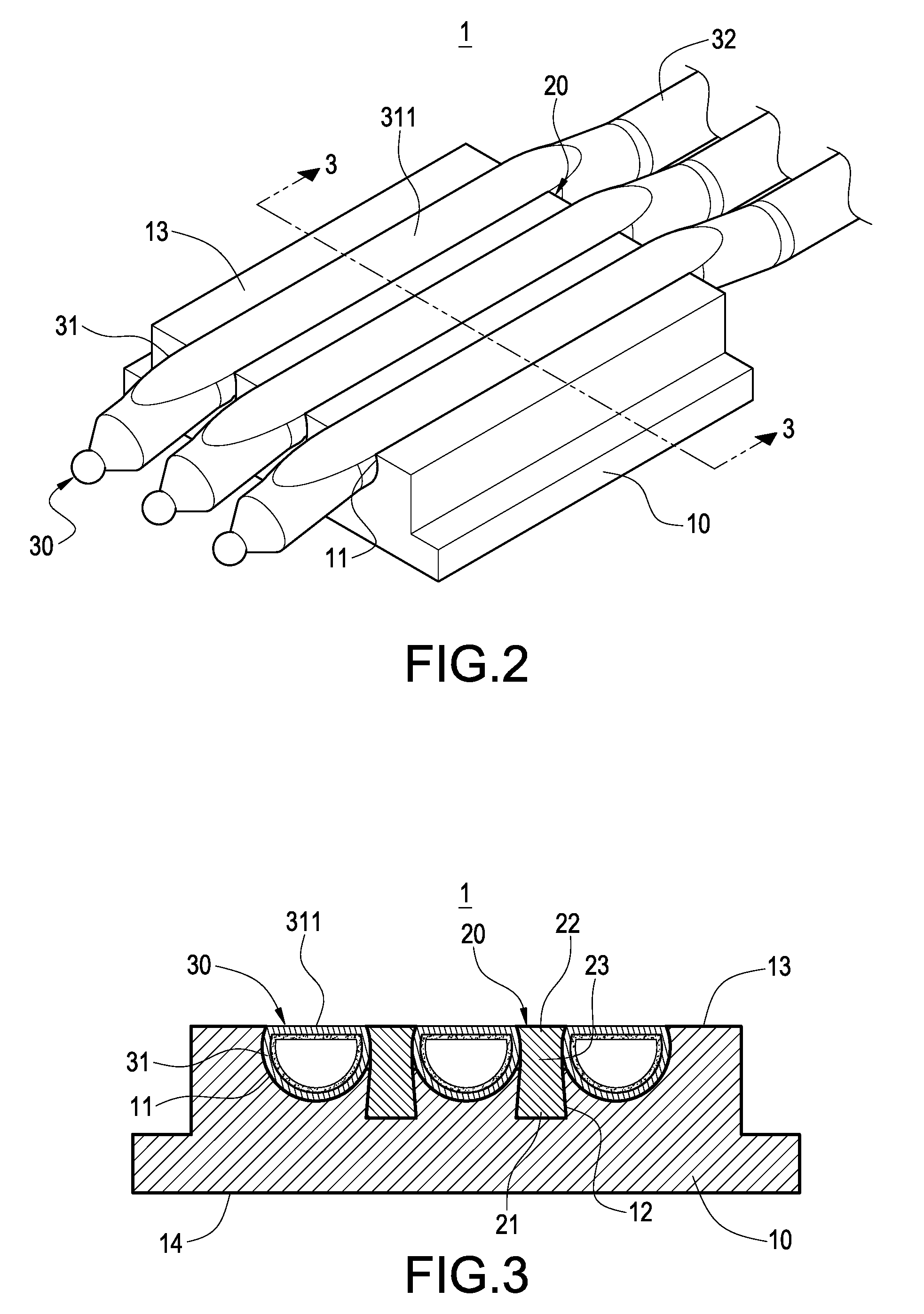
[0020]Please refer to FIG. 1 through FIG. 3. A thermally conductive module 1 according to the present invention is comprised of a base seat 1, a thermally conductive copper block 20 and a heat pipe 30.

[0021]The base seat 10 has a side face 13 and another side face 14 corresponding to the side face 13. An accommodation slot 11 is arranged on the side face 13 and a fixing slot 12 is arranged at a lateral side of the accommodation slot 11. The fixing slot 12 can be a dovetail slot. One or more cooling fins can be attached to another side face 14, as shown in FIG. 4. The base seat can be made by an aluminum extrusion or of...


PUM


Abstract

A thermally conductive module includes a base seat, a thermally conductive copper block and a heat pipe. A side face of the base seat is arranged an accommodation slot, a lateral side of which is arranged a fixing slot. The thermally conductive copper seat is inset into the fixing slot and combined therewith. The heat pipe has a heated section, on which a plane is configured and flush with the side face of the base seat, and which is accommodated by being clamped between the accommodation slot and the thermally conductive copper block. Thus, it is possible to effectively boost the thermally conductive speed and thermally conductive performance entirely.

Description

BACKGROUND OF THE INVENTION[0001]1. Field of the Invention[0002]The present invention in general relates to a thermally conductive module, in particular, to a thermally conductive module having heat pipe and thermally conductive copper block.[0003]2. Description of Prior Art[0004]Heat pipe has the characteristics of high heat-transferring capability, high thermal conductivity, light weight, simple structure and a variety of functions, and it also can transfer a large amount of heat, consumes no power and has the merit of low cost so, in use, it is usually integrated with a base seat to constitute a thermally conductive module, which has been applied to the thermal conduction of electronic heating elements, the heat generated from which can be dissipated quickly, thus, effectively solving the thermally concentrating phenomenon faced by electronic heating elements in current stage.[0005]The thermally conductive module according to prior arts is provided by attaching to a surface of he...

Claims


Application Information

Patent Timeline
IPC IPC(8): F28D15/02F28F7/00
CPCF28D15/0275
Inventor HUANG, SHIH-WEIHSIEH, YI-JEN
Owner HUANG SHIH WEI
Learn More