Damp-proof terminal box

A terminal box and box technology, applied in electrical components, substation/switch layout details, etc., can solve the problems of abnormal operation, easy damping of the box, increasing the burden of moisture-proof equipment such as drying boxes and exhaust fan heaters, etc. Uniform temperature distribution, improved moisture-proof effect, improved moisture-removal efficiency

Active Publication Date: 2013-08-14
STATE GRID CORP OF CHINA +2
View PDF5 Cites 19 Cited by
  • Summary
  • Abstract
  • Description
  • Claims
  • Application Information

AI Technical Summary

Problems solved by technology

[0002] As is known, the terminal box mainly includes a box body, a top cover arranged on the top of the box body, a terminal bracket arranged in the box body, and a connecting terminal arranged on the terminal bracket. Under degraded conditions, especially in the rainy season, the inside of the box is prone to moisture, condensation and water accumulation. The box is damp, which will rust the terminal row screws and connecting pieces, make the secondary terminals poor contact, and cause the current circuit terminals to heat up or even open. , resulting in protection refusal or misoperation, causing accidents; the transformer voltage caused by moisture and the poor contact of the switch and temperature signal terminals will cause abnormal operation of the measurement and control and protection devices, and false signals, resulting in misjudgments by operators and wrong analysis
Aiming at the above problems, there are various moisture-proof solutions on the market, such as the moisture-proof terminal box disclosed in the patent No. 200820199458.4, which is arranged at the air inlet through the air inlet, the exhaust hole, the exhaust fan, and the drying box for storing the desiccant. The heater and temperature sensor realize the moisture-proof of the terminal box, but it ignores the sealing requirements of the terminal box while preventing moisture. The exhaust hole and the air inlet hole increase the way for moisture to enter the terminal box, especially in humid thunderstorm weather , increasing the burden on moisture-proof equipment such as drying ovens, exhaust fans, and heaters

Method used


Image

  • Damp-proof terminal box
  • Damp-proof terminal box
  • Damp-proof terminal box

Examples


Embodiment Construction

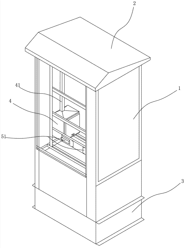
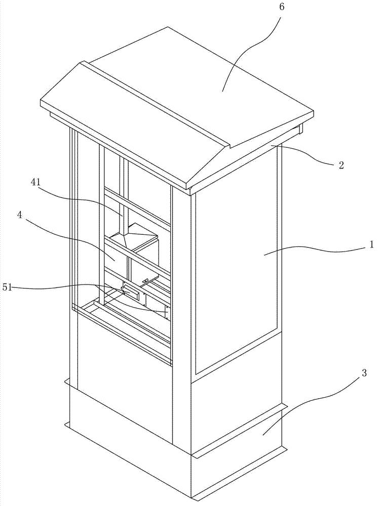
[0032] refer to Figure 1 to Figure 9 As shown, a moisture-proof terminal box includes a base 3, a box body 1 set on the base 3, a top cover 2 set on the top of the box body 1, a sunshade cover 6 set above the top cover 2 and a box body 1 In the drying box 4, the top of the sunshade cover 6 is provided with a vent 61 with side openings.

[0033] The top cover 2 is composed of an outer cover body and an inner cover body arranged in the outer cover body. A condensation chamber A is formed between the outer cover body and the inner cover body. The slanting plate 24 and the two side plates 23 are spliced ​​together. The first slanting plate 25 is larger than the second slanting plate 24. The first slanting plate 25 is provided with a dehumidification hole 261 connecting the inside of the box body 1 and the dew chamber A to drain moisture. An exhaust fan 27 is arranged on the hole 261, and the upper end surface of the first inclined plate 25 is provided with a condensation net 26 ...


PUM


Abstract

A damp-proof terminal box comprises a box body and a top cover arranged at the top of the box body. The damp-proof terminal box is characterized in that the top cover comprises an outer cover body and an inner cover body arranged in the outer cover body; a condensation cavity is formed between the outer cover body and the inner cover body; a dehumidification hole communicated with the interior of the box body and the condensation cavity is formed in the inner cover body; an exhaust blower is arranged on the dehumidification hole; condensation screens are arranged in the condensation cavity; breathing holes communicated with the exterior and the condensation cavity are formed in the bottom of the outer cover body; and the exhaust blower lead moisture in the box body into the condensation cavity, the moisture condensed into water droplets after encountering the condensation screens, and the water droplets are discharged to the exterior of box body through the breathing holes. Owing to the arrangement of the condensation cavity, the leak tightness of the box body can be ensured, the moisture is effectively prevented from entering the box body through a dehumidification channel, moisture supplement is cut off from the source, and the damp-proof effect of the damp-proof terminal box is effectively improved.

Description

technical field [0001] The invention relates to a terminal box. Background technique [0002] As is known, the terminal box mainly includes a box body, a top cover arranged on the top of the box body, a terminal bracket arranged in the box body, and a connecting terminal arranged on the terminal bracket. Under degraded conditions, especially in the rainy season, the inside of the box is prone to moisture, condensation and water accumulation. The box is damp, which will rust the terminal row screws and connecting pieces, make the secondary terminals poor contact, and cause the current circuit terminals to heat up or even open. , resulting in protection refusal or misoperation, causing accidents; the transformer voltage caused by moisture and the poor contact of switch and temperature signal terminals will cause abnormal operation of measurement and control and protection devices, and false signals, resulting in misjudgments by operators and wrong analysis. Aiming at the abov...

Claims


Application Information

Patent Timeline
Patent Type & Authority Applications(China)
IPC IPC(8): H02B1/46H02G3/08
Inventor 沈谢林王铮赖海凌
Owner STATE GRID CORP OF CHINA
Why Eureka
Try Eureka