Thermal control device

a control device and thermal control technology, applied in the direction of indirect heat exchangers, machines using electric/magnetic effects, lighting and heating apparatus, etc., can solve the problem of increasing the mass and achieve the effect of increasing the thermal conductivity of the loop heat pip

Inactive Publication Date: 2012-08-09
IBERICA DEL ESPACIO
View PDF4 Cites 20 Cited by
  • Summary
  • Abstract
  • Description
  • Claims
  • Application Information

AI Technical Summary

Benefits of technology

[0017]With the method and loop heat pipe of the invention,

Problems solved by technology

However, the purpose of the application of the thermal electrical cooler in loop heat pipes in the above-mentioned documents does not include the problem related to the existing need of increasing loop heat pipe thermal conductance by means of compen

Method used


Image

  • Thermal control device
  • Thermal control device
  • Thermal control device

Examples


Embodiment Construction

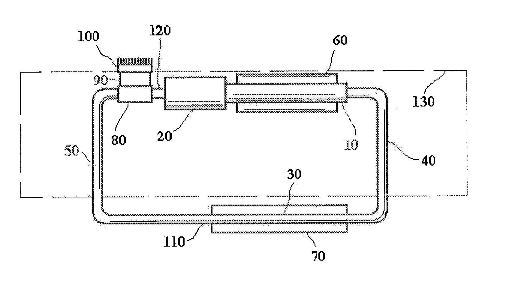
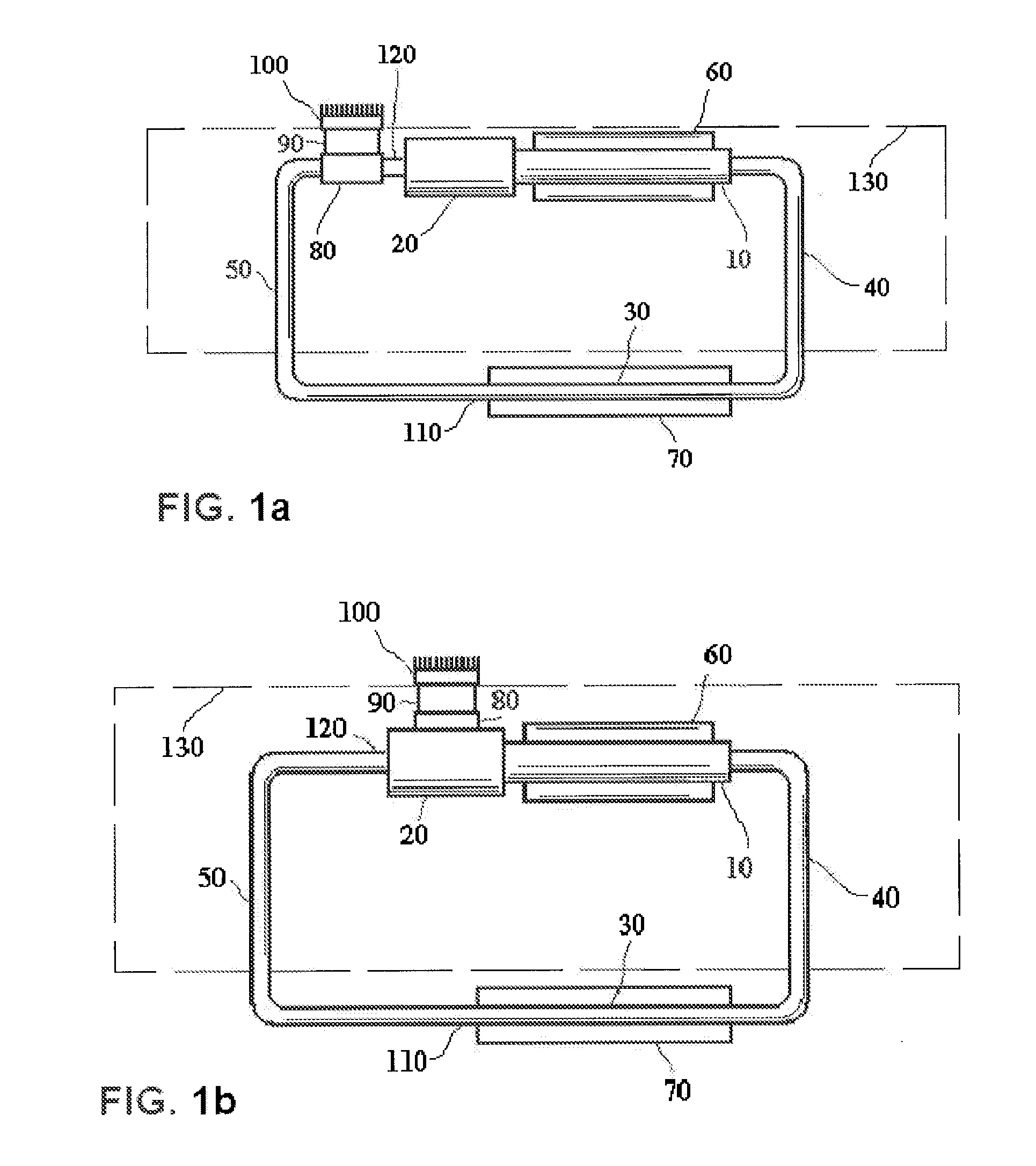
[0026]A loop heat pipe, as shown in FIG. 1, is an effective heat transfer or thermal control device, comprising an evaporator 10, a compensation chamber 20, a condenser 30, a vapour transport line 40 and a liquid transport line 50 connecting them. The evaporator 10, typically cylindrical, is located inside an evaporator saddle 60, to which heat dissipating devices are attached. The condenser 30 is embedded to a radiator 70, in order to increase the area of heat rejection.

[0027]The evaporator 10 comprises inside a porous wick, and the loop heat pipe is charged with working fluid. Part of the inner volume of the loop heat pipe (wick, liquid transport line 50, and the compensation chamber 20 and the condenser 30, partially) is filled with the liquid phase of the working fluid, while part of the inner volume of the loop heat pipe (the vapour transport line 40, partially the compensation chamber 20 and the condenser 30, as well as vapour channels and grooves in the evaporator 10) is fill...


PUM


Abstract

The invention refers to a thermal control device for controlling the temperature of a heat source by means of transferring heat from the heat source to the ambient environment, through the circulation of a fluid in the device, said device comprising an evaporator (10) collecting heat from the heat source, a condenser (30) rejecting heat to the ambient environment, a compensation chamber (20), and liquid (50) and vapor (40) transport lines connecting the evaporator (10) and the condenser (30), the fluid flowing through said transport lines (40, 50), the device further comprising a thermal electrical cooler (90), the thermal electrical cooler (90) further comprising a thermal saddle (80) attached to the cold side of the thermal electrical cooler (90), and a thermal radiator (100) attached to the hot side of the thermal electrical cooler (90), such that heat is rejected to the ambient environment directly through the thermal radiator (100), when the thermal control device operates in a hot environment, the ambient temperature surrounding the liquid transport line (50) being higher than the temperature of liquid in the exit (110) of the condenser (30).

Description

FIELD OF THE INVENTION[0001]The present invention relates to improvements in a thermal control device, in particular to a method for increasing the thermal conductance of a thermal control device and to an apparatus to perform such method.BACKGROUND OF THE INVENTION[0002]At present, thermal control of electronics and computer equipment is the key element of proper operation of these kind of equipments. The most commonly known thermal devices used for controlling thermal loads in electronics are the so called two phase heat transfer loops, which are also known in engineering practice as loop heat pipes.[0003]The purpose of these known loop heat pipes is to transfer heat between a heat source (for instance, an electronic element) and a heat sink (for instance, a radiator). A loop heat pipe is a closed, hermetically sealed circuit, which is partially filled by a working fluid, which is called heat carrier. Known loop heat pipes operate in the saturation curve of the working fluid, such...

Claims


Application Information

Patent Timeline
IPC IPC(8): F25B21/00
CPCF25B21/02F28D15/0266F28D15/0275F28D15/04H01L23/38H01L2924/0002H01L23/427H01L2924/00
Inventor SEPULVEDA, ALEJANDRO TORRESMISHKINIS, DONATASKULAKOV, ANDREI
Owner IBERICA DEL ESPACIO
Why Eureka
Try Eureka