Filament Winding Apparatus

a technology of winding apparatus and filament, which is applied in the manufacture of coils, inductance/transformers/magnets, transportation and packaging, etc., can solve the problems of limit the reduction of the variation of the distance between the liner and the guide portion, reduce the variation of the distance between the liner and each of the guide portions, and reduce the fluctuations of the winding operation.

Active Publication Date: 2010-02-11
MURATA MASCH LTD
View PDF1 Cites 28 Cited by
  • Summary
  • Abstract
  • Description
  • Claims
  • Application Information

AI Technical Summary

Benefits of technology

[0010]In order to overcome the problems described above, the present invention provides a filament winding apparatus that reduces fluctuations in a winding operation by reducing the variation of a distance from a liner to a plurality of guide portions.
[0016]In the filament winding apparatus according to an embodiment of the present invention, by bringing the guide portions close to the liner while rotating the leading end portions of the guide portions about their respective axes, the guide portions can be brought close to the liner until the leading end portions of the guide portions overlap in the thickness direction. Accordingly, variation of the distance between the liner and each of the guide portions is reduced, thereby reducing fluctuations in a winding operation.
[0017]In the filament winding apparatus according to an embodiment of the present invention, by rotating the guide portions about their respective axes by the rotation mechanism, and by sliding the first supporting members, i.e., by sliding the guide portions in the radius direction of the liner by the slide mechanism, the guide portions can be brought close to the liner until the leading end portions of the guide portions overlap in the thickness direction. Accordingly, variation of the distance between the liner and each of the guide portions is reduced, thereby reducing fluctuations in a winding operation.
[0018]In the filament winding apparatus according to an embodiment of the present invention, by bringing the guide portions close to the liner while rotating the leading end portions of the guide portions about their respective axes, and by changing the phases around the axis of the liner with respect to each of the plurality of groups by the phase change mechanism, the guide portions can be brought close to the liner until the leading end portions of the guide portions overlap in the thickness direction, and the fiber bundles guided from the guide portions of the plurality of groups can be wound around the liner. Accordingly, variation of the distance between the liner and each of the guide portions is further reduced, fluctuations in the winding operation are also reduced, and a greater number of fiber bundles can be wound around the liner.
[0019]In the filament winding apparatus according to an embodiment of the present invention, since the distance from each of the leading end portions of the guide portions to the liner is maintained constant, the fiber bundles can be wound around the liner while maintaining a constant tension, and fluctuations in the winding operation are reduced.

Problems solved by technology

As a result, leading end portions of the guide portions collide and interfere with each other when the guide portions are moved in the radius direction of the liner to be close to the liner, and therefore, there are limitations to the reduction of the variation of the distance from the liner to the guide portions.

Method used


Image

  • Filament Winding Apparatus
  • Filament Winding Apparatus
  • Filament Winding Apparatus

Examples


Embodiment Construction

[0027]A filament winding apparatus 1 according to an embodiment of the present invention will now be described.

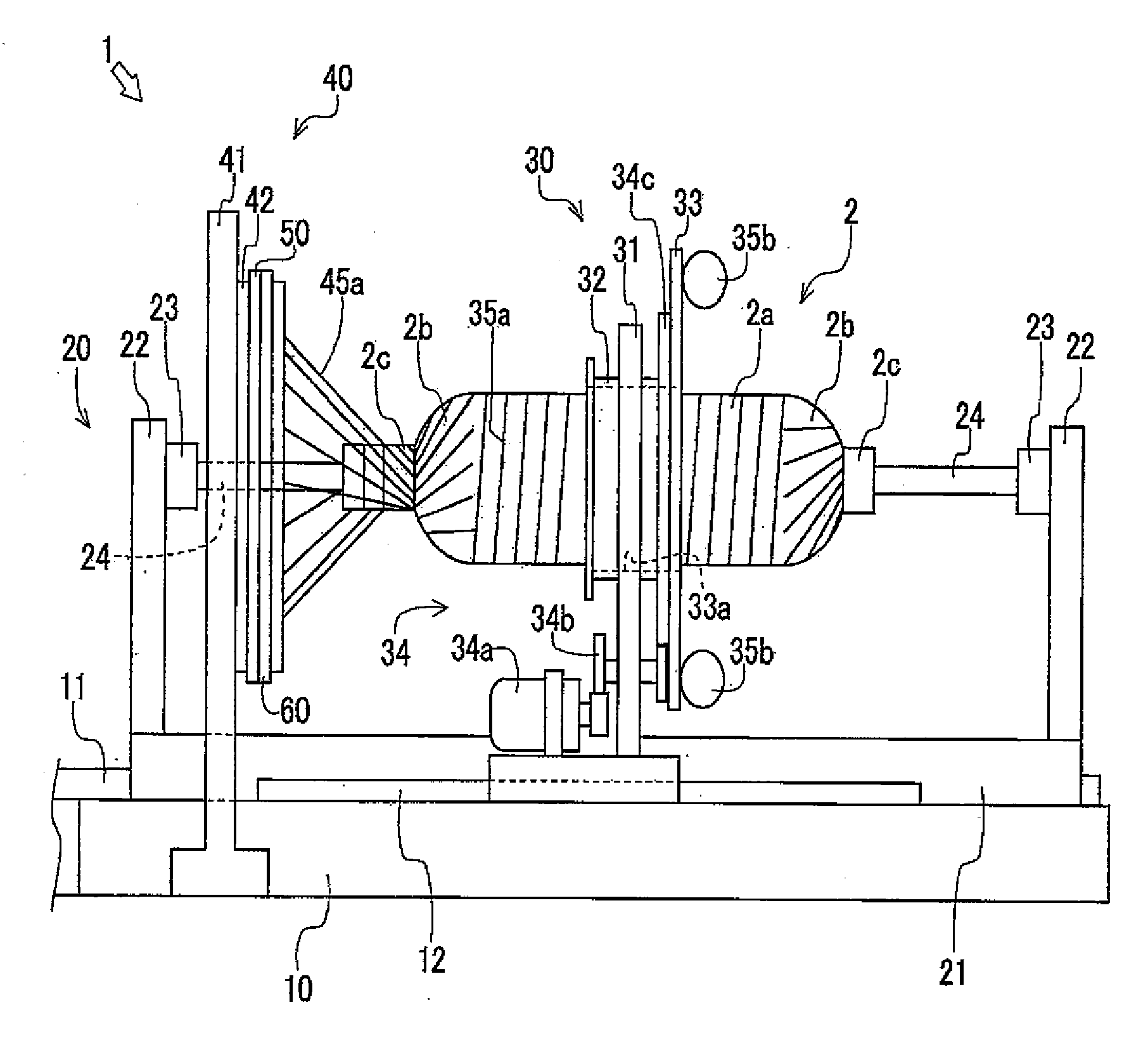
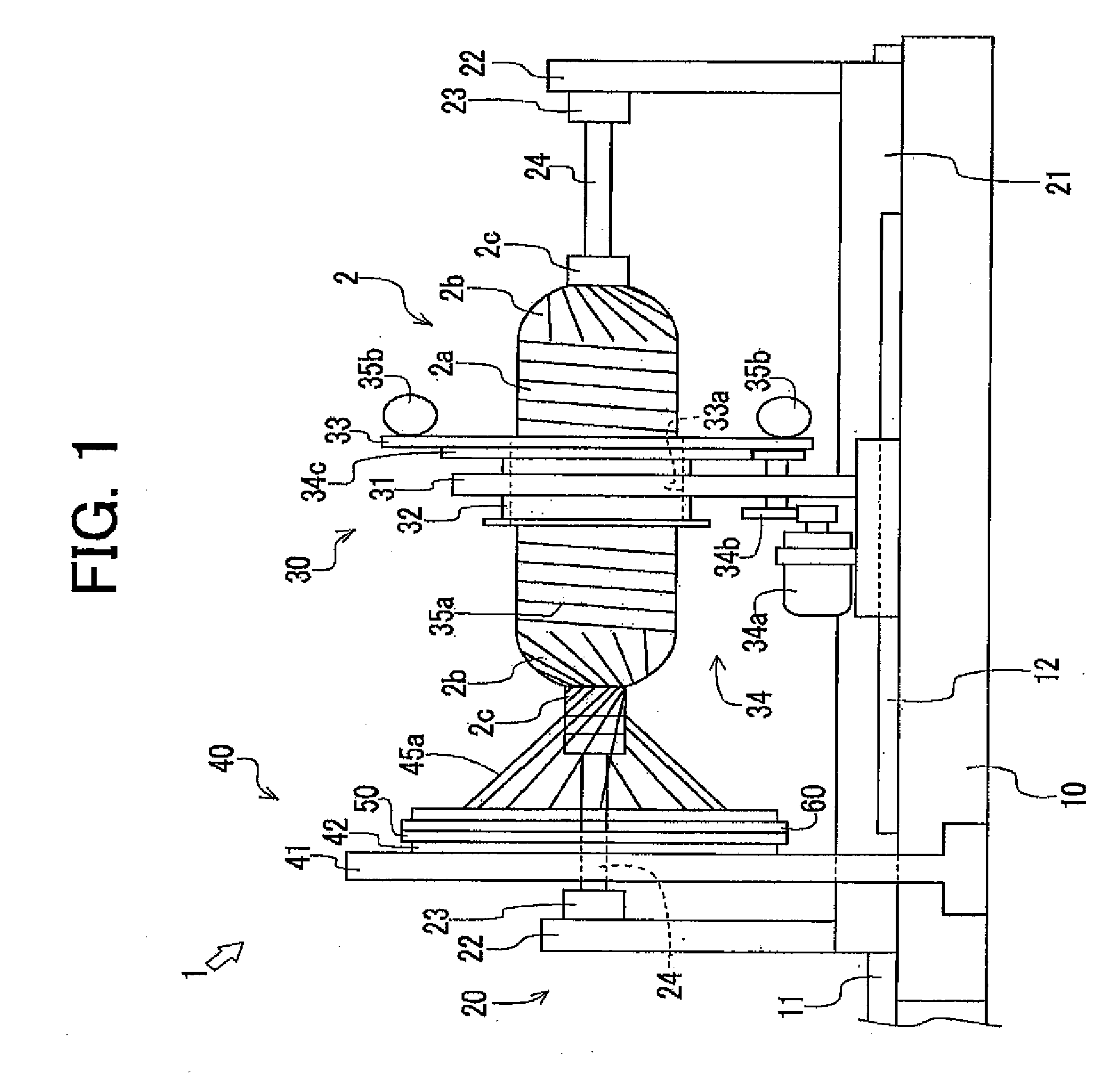
[0028]As illustrated in FIG. 1, the filament winding apparatus 1 winds fiber bundles 35a and 45a around a liner 2 and includes a machine frame 10, a liner supporting unit 20, a hoop winding unit 30, and a helical winding unit 40. The liner 2 integrally includes a first cylindrical portion 2a having a constant radius, hemisphere portions 2b, 2b provided at both ends of the first cylindrical portion 2a, and second cylindrical portions 2c, 2c provided at end portions of the hemisphere portions 2b, 2b. The radius of the liner 2 continuously changes from the first cylindrical portion 2a to each of the hemisphere portions 2b and to each of the second cylindrical portions 2c. The radius of the second cylindrical portions 2c is smaller than that of the first cylindrical portion 2a. The liner 2 is composed of a metal container made of high-strength aluminum or stainless steel etc. o...


PUM

PropertyMeasurementUnit
sizeaaaaaaaaaa
thicknessaaaaaaaaaa
radiusaaaaaaaaaa

Abstract

A filament winding apparatus reduces fluctuations in a winding operation by bringing a plurality of guide portions that guide fiber bundles to a liner close to the liner in a winding unit. Each of the guide portions is a tubular member having a guide hole penetrated from a base end to a leading end portion. The leading end portion has a smaller thickness width. Each of the guide portions guides a second fiber bundle to the liner by passing the second fiber bundle from a side of the base end portion to a side of the leading end portion of the guide hole. By rotating each of the guide portions about an axis of the guide portion, and by sliding the guide portions in the radius direction of the liner, the guide portions can be brought close to the liner.

Description

CROSS-REFERENCE TO RELATED APPLICATIONS[0001]This application claims the benefit of priority under 35 USC 119 of Japanese application no. 2008-202197, filed on Aug. 5, 2008, which is incorporated herein by reference.BACKGROUND OF THE INVENTION[0002]1. Field of the Invention[0003]The present invention relates to a filament winding apparatus.[0004]2. Description of the Related Art[0005]A well-known filament winding apparatus includes a hoop winding unit and a helical winding unit and forms reinforced layers by alternately performing a hoop winding operation by the hoop winding unit and a helical winding operation by the helical winding unit repeatedly on a liner and thus winding fiber bundles around the liner.[0006]When the helical winding unit performs the helical winding operation, the liner moves in an axial direction while being rotated at constant speed, and the fiber bundle is supplied from the helical winding unit and wound around the liner. In a conventional art, when the fibe...

Claims


Application Information

Patent Timeline
Patent Type & Authority Applications(United States)
IPC IPC(8): B65H81/06B65H81/00
CPCB29C53/602B29C53/8016B29C53/64
Inventor TANIGAWA, MOTOHIROUOZUMI, TADASHI
Owner MURATA MASCH LTD
Why Eureka
Try Eureka