
Neutron Polarization Apparatus

a technology of neutron polarization and apparatus, which is applied in the field of neutron polarization apparatus, can solve the problems of difficult fabrication of a neutron polarization apparatus with practical functions by using an available magnet, huge apparatus size, and considered impractical, and achieves high transmittance, high polarization, and high transmittance.

Inactive Publication Date: 2010-02-11
RIKEN
View PDF4 Cites 7 Cited by
  • Summary
  • Abstract
  • Description
  • Claims
  • Application Information

AI Technical Summary

Benefits of technology

[0009]According to the present invention, employing any of the configurations described above allows an excellent neutron polarization apparatus capable of polarizing a neutron so that it has a high polarization unavailable in the prior art.
[0010]Further, the present invention can provide a neutron polarization apparatus characterized by, in addition to the above excellent advantage, a high transmittance (an extremely high transmittance, no absorption or scattering, and an extremely high efficiency), linear installation capability (beam axis controlling capability), maintenance-free, high stability, and compactness (the design is believed to be optimum in a sense that the apparatus is compact as a magnetic field-based polarizing element).

Problems solved by technology

In practice, however, from the fact that the interaction energy between the spin of a neutron and a magnetic field is extremely small, fabrication of a neutron polarization apparatus with practical functions by using an available magnet has been believed to be difficult.
Further, even if such a neutron polarization apparatus can be fabricated, the apparatus will be huge in size, and hence has been considered impractical.
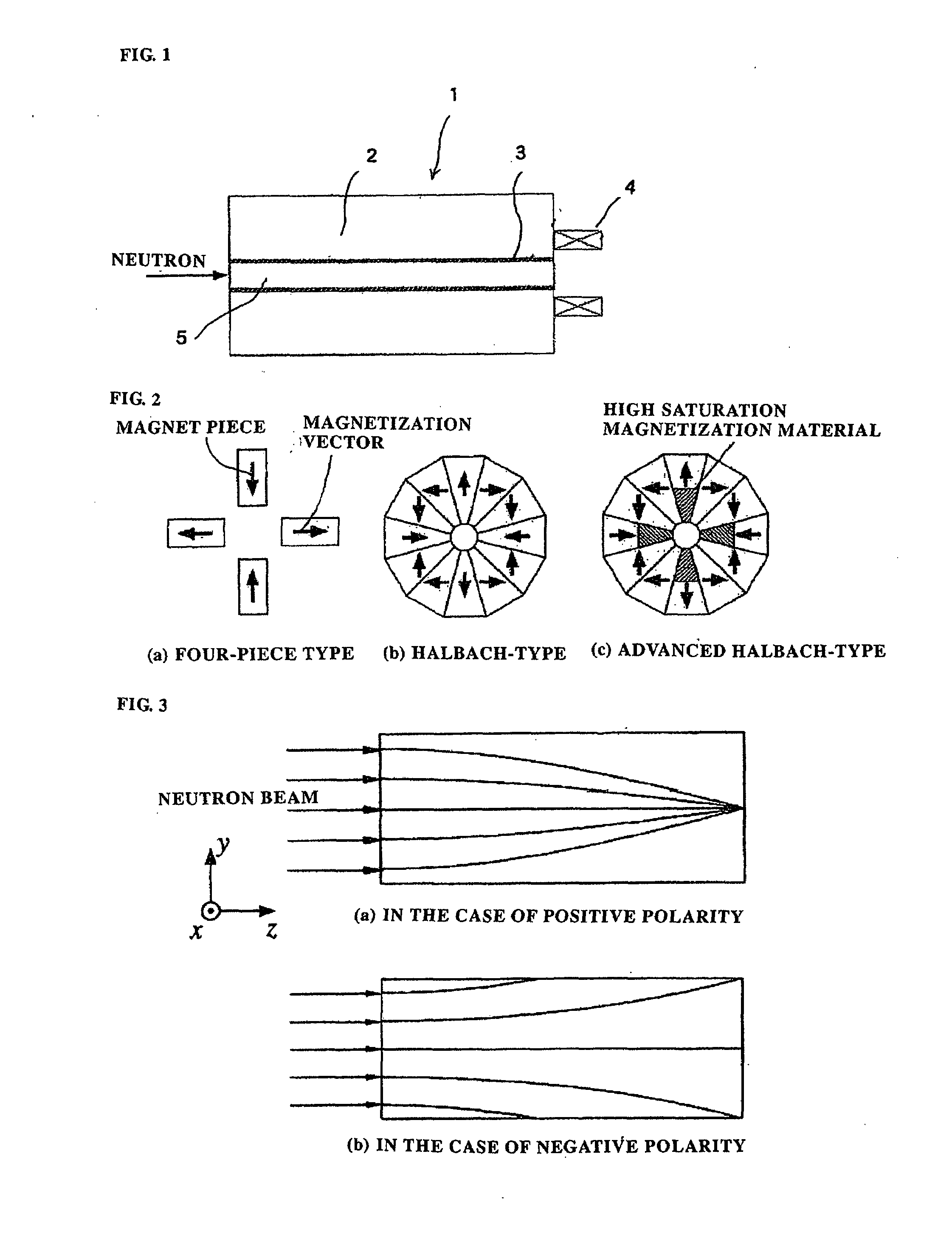
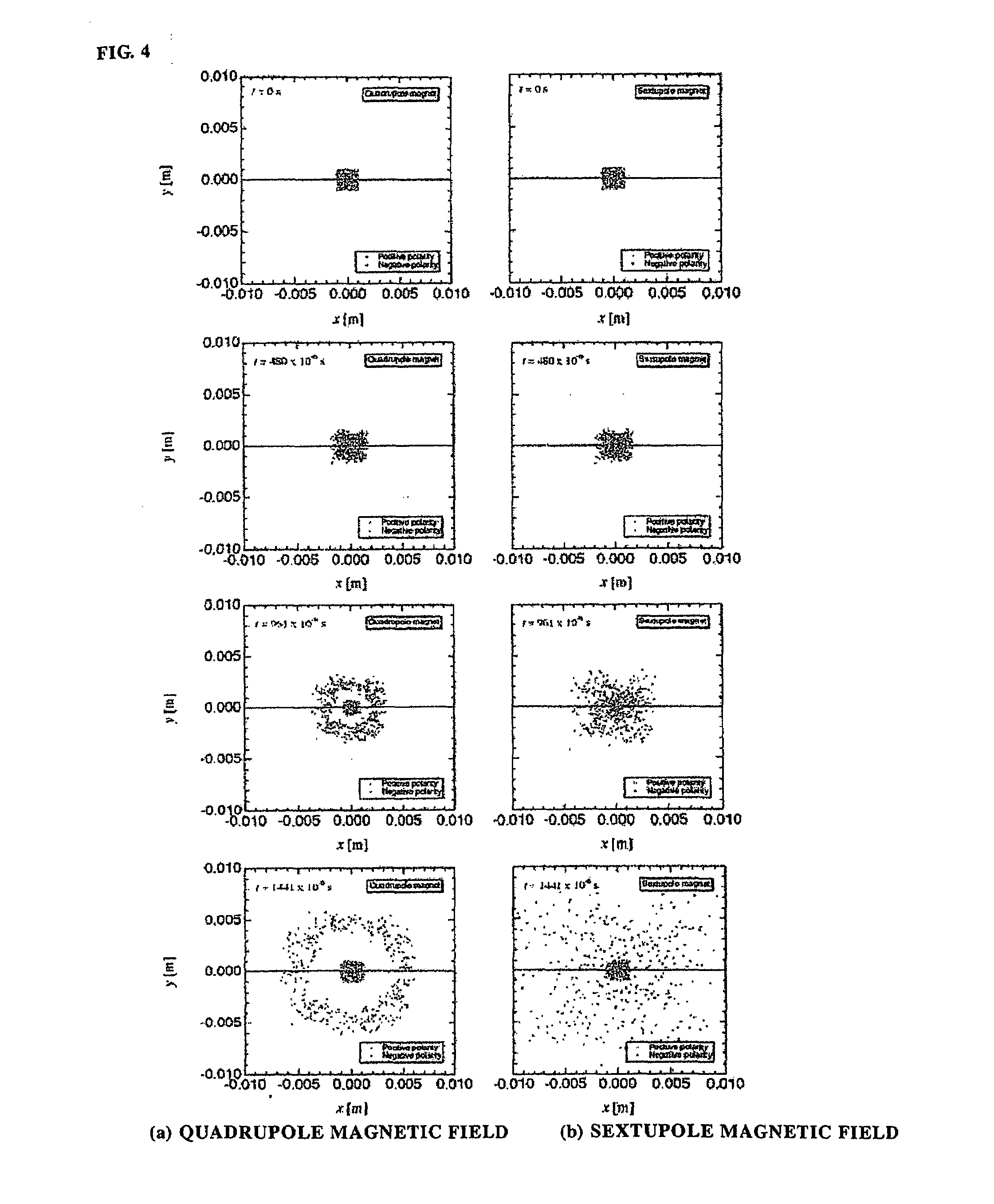
However, if incident neutrons contain negative polarity components, such components diverge through the sextupole magnet and spread over the detector surface, resulting in an increased background level.
However, it has been difficult to obtain higher polarization.

Method used


Image

  • Neutron Polarization Apparatus
  • Neutron Polarization Apparatus
  • Neutron Polarization Apparatus

Examples


examples

[0037]FIG. 5 is a cross-sectional view diagrammatically showing the configuration of an experimental setup using the neutron polarization apparatus of an example according to the present invention.

[0038]In FIG. 5, reference numeral (11) denotes the neutron polarization apparatus including a Halbach-type quadrupole magnet (12) (hereinafter also simply referred to as a quadrupole magnet (12)). The Halbach-type quadrupole magnet (12) has an axial length of approximately 600 mm. In the Halbach-type quadrupole magnet (12) is disposed a tubular neutron absorber (13) made of Cd (hereinafter also referred to as Cd tube), which extends in the axial direction and has a 5 mm-diameter hollow portion through which neutrons pass. The neutron absorber (13) is provided to prevent neutrons from being reflected off the inner surface of the quadrupole magnet (12), and formed of a 0.5 mm-thick, spirally coiled Cd plate. At the downstream end of the quadrupole magnet (12) is disposed a solenoid coil (Sc...


PUM


Abstract

A neutron polarization apparatus is provided that provides a neutron beam polarized by an interaction between a spin of a neutron in an incident neutron beam and a magnetic field. The apparatus includes a quadrupole magnet (2) disposed around a passage of a neutron beam, a tubular neutron absorber (3) provided in the quadrupole magnet (2) along am axial direction of the neutron beam, and a solenoid coil (4) disposed at an exit of the quadrupole magnet (2), adiabatically coupling the quadrupole magnetic field produced by the quadrupole magnet (2) and applying a bipolar magnetic field. The neutron polarization apparatus can polarize a neutron with a high polarization unavailable in the prior art.

Description

TECHNICAL FIELD[0001]The present invention relates to a neutron polarization apparatus capable of polarizing a neutron so that it has an extremely high polarization.BACKGROUND ART[0002]A polarized neutron is an extremely useful probe in neutron scattering studies, and essential in elucidation of magnetic structures, studies on dynamics, such as relaxation phenomena using neutron spin echo techniques, and removal of incoherent scattering. Further, a polarized neutron plays a significantly important role in neutron-based studies in fundamental physics. To obtain a polarized neutron, methods using magnetic crystals or magnetic multilayer films have been available, and in recent years, a method using polarized 3He gas is available. Development of neutron polarization apparatus having novel features and excellent performance is significantly important to make advances in techniques used in neutron scattering study.[0003]The concept of using the interaction between the spin of a neutron a...

Claims


Application Information

Patent Timeline
IPC IPC(8): H05H3/02
CPCG21K1/093H05H3/06G21K1/16
Inventor SHIMIZU, HIROHIKOSUZUKI, JUN-ICHIOKU, TAKAYUKI
Owner RIKEN
Learn More