Rotating electric machine

a technology of rotating electric machines and rotating shafts, applied in the direction of mechanical energy handling, mechanical apparatus, engine components, etc., can solve the problem of large attractive force, achieve the effect of increasing effective producing the shaft supporting force, and reducing the angular pulsation of the shaft supporting for

Inactive Publication Date: 2010-02-11
TOKYO UNIVERSITY OF SCIENCE
View PDF4 Cites 20 Cited by
  • Summary
  • Abstract
  • Description
  • Claims
  • Application Information

AI Technical Summary

Benefits of technology

[0030]In the rotating electric machine according to the first aspect of the present invention, the rotor has the second rotor section for effectively producing a shaft supporting force, thereby making it possible to increase a shaft supporting force in relation to the driving current, and in addition can reduce the angular pulsation of the shaft supporting force. As a result, there is an effect of making it possible to produce an adequate shaft supporting force (magnetic supporting force) even in a case in which the gap length between the rotor and the stator is long.
[0031]In the rotating electric machine according to the second aspect of the present invention, the first rotor section has the first rotor core and the permanent magnet or the inductive conductor carrying an induced current, which is mounted to the first rotor core, and the second rotor section has the second rotor core. As a result, there is an effect that the first rotor section can effectively produce a torque and the second rotor section can effectively produce a shaft supporting force.
[0032]In the rotating electric machine according to the third aspect of the present invention, the first rotor section is of a consequent-pole structure. As a result, there is an effect that both a torque and a shaft supporting force can be effectively produced.
[0033]In the rotating electric machine according to the fourth aspect of the present invention, the permanent magnet is provided in plurality in the first rotor section, the first rotor core is of a cylindrical shape, the permanent magnets are mounted inside the first rotor core, and outer surfaces of the adjacent permanent magnets in a radial direction are of

Problems solved by technology

Furthermore, since a permanent magnet is used in the bearingless rotating machine,

Method used


Image

  • Rotating electric machine
  • Rotating electric machine
  • Rotating electric machine

Examples


Embodiment Construction

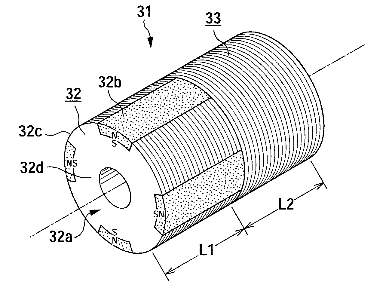
[0057]A bearingless motor, which is an example of the rotating electric machine according to an embodiment of the present invention, is hereinafter described with reference to the drawings. Here, since a configuration of a rotor is different from that of the two rotors 12a and 12b described in FIG. 15, the rotor is denoted with a reference numeral 31. It should be noted that, since the entire configuration of a brushless motor is similar to that in FIG. 15, a description thereof is omitted.

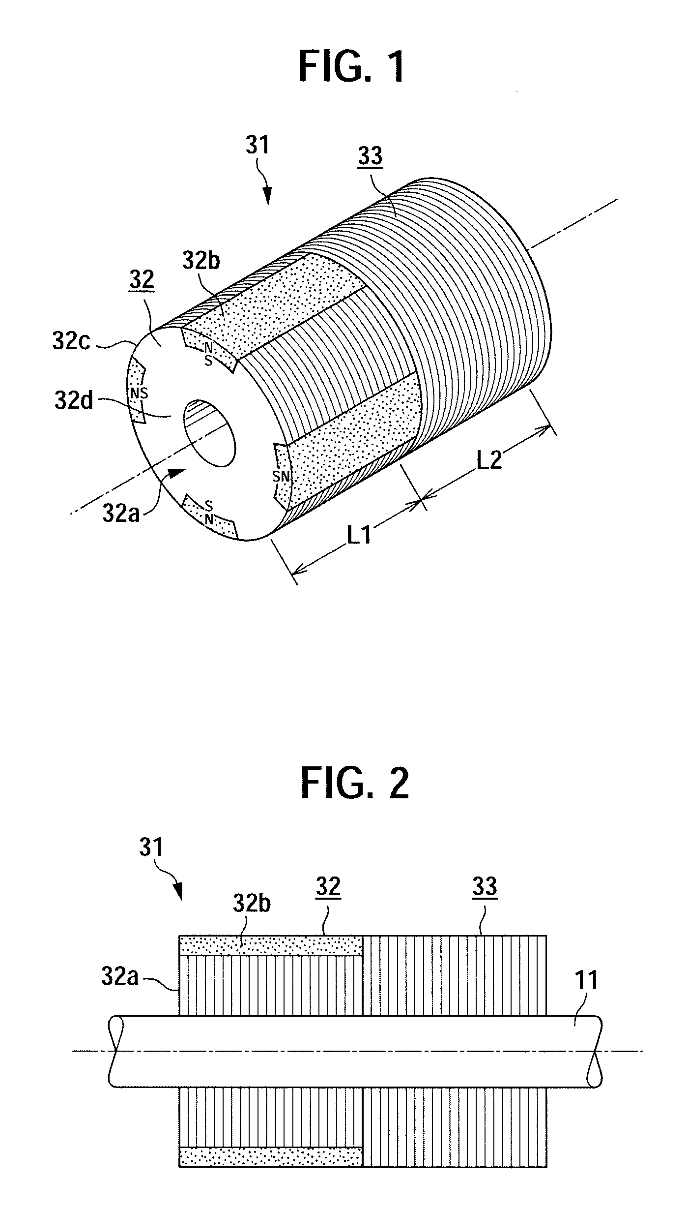
[0058]FIG. 1 is a perspective view showing an example of a rotor 31 used in a bearingless motor according to one embodiment of the present invention. FIG. 2 is a longitudinal sectional view of the rotor 31 shown in FIG. 1. In FIGS. 1 and 2, the rotor 31 has a first rotor section 32 and a second rotor section 33. The first rotor section 32 and the second rotor section and 33 are coaxially arranged, and a rotational axis (main shaft) 11 is passed through the center thereof. The first rotor section 3...


PUM


Abstract

A rotating electric machine in which an adequate magnetic supporting force can be produced even when the gap length of the rotator is long. The rotating electric machine comprises a rotator (31) mounted on the main shaft and a stator so provided as to enclose the rotator. The rotator has a first rotator section (32) producing a torque in the circumferential direction of the main shaft or the torque and the supporting force and a second rotator section (33) producing a shaft supporting force outward in the radial direction of the main shaft. The first and second rotator sections are arranged in tandem along the main shaft.

Description

TECHNICAL FIELD[0001]The present invention relates to a rotating electric machine such as an electric motor. The present invention particularly relates to a so-called bearingless rotating machine that eliminates the need for mechanical shaft bearings such as bearings by supporting a rotor with a magnetic force.BACKGROUND ART[0002]Generally, demand for higher speed and higher power has been increasing for an electric motor (motor) that is one of a rotating electric machine used in machine tools, a turbo-molecular pump, a flywheel and the like. So-called magnetic bearings may be applied to such a motor in some cases in order to solve problems such as speed limitation and conservation of the shaft bearings.[0003]Rotating electric machines using the magnetic bearings are referred to as a bearingless rotating machine. In such a bearingless rotating machine, there are examples aimed at realizing a magnetic bearing function and a motor function in a single rotating electric machine. For ex...

Claims


Application Information

Patent Timeline
IPC IPC(8): H02K7/09
CPCF16C32/0459H02K7/09H02K1/2746F16C32/0493F16C2380/26F16C2360/45
Inventor CHIBA, AKIRATAKEMOTO, MASATSUGUFUKAO, TADASHI
Owner TOKYO UNIVERSITY OF SCIENCE
Why Eureka
Try Eureka