Printing apparatus and control method of the same

a control method and printing technology, applied in printing, typewriters, other printing apparatus, etc., can solve the problems of deteriorating printing precision, affecting the accuracy of printing,

Inactive Publication Date: 2010-02-11
SEIKO EPSON CORP
View PDF3 Cites 6 Cited by
  • Summary
  • Abstract
  • Description
  • Claims
  • Application Information

AI Technical Summary

Benefits of technology

[0023]In the method of controlling the printing apparatus according to the fifth aspect of the invention, it is possible ...

Problems solved by technology

In this kind of printing apparatus, when the printing process is performed in the state where a posture of the disc tray with respect to a transport direction of the transport device is skewed (hereinafter, simply referred to as “a skew”), a positional deviation occurs between the label surface of the optical disc and a printing target position, which may deteriorate the printing precision.
Likewise, the shape, the arrangement, or the like of the guide member is limited in many cases.
For this reason, in the known technology disclosed in JP-A-2006-82323, a problem arises in that the skew of the disc tray cannot be corrected with high precision.
Further, since the disc tray is repeatedly used, the disc tray is also abraded upon performing the transport operation using the transport device.
For this reason, in the known technology for correcting the skew of the disc tray by alternately repeating the normal transport operation...

Method used


Image

  • Printing apparatus and control method of the same
  • Printing apparatus and control method of the same
  • Printing apparatus and control method of the same

Examples


first embodiment

Ink Jet Printer of the Invention

[0040]An ink jet printer 50 as “a printing apparatus” according to a first embodiment of the invention will be described with reference to FIGS. 1 to 8.

[0041]First, a schematic configuration of the ink jet printer 50 according to the first embodiment will be described with reference to FIGS. 1 to 3.

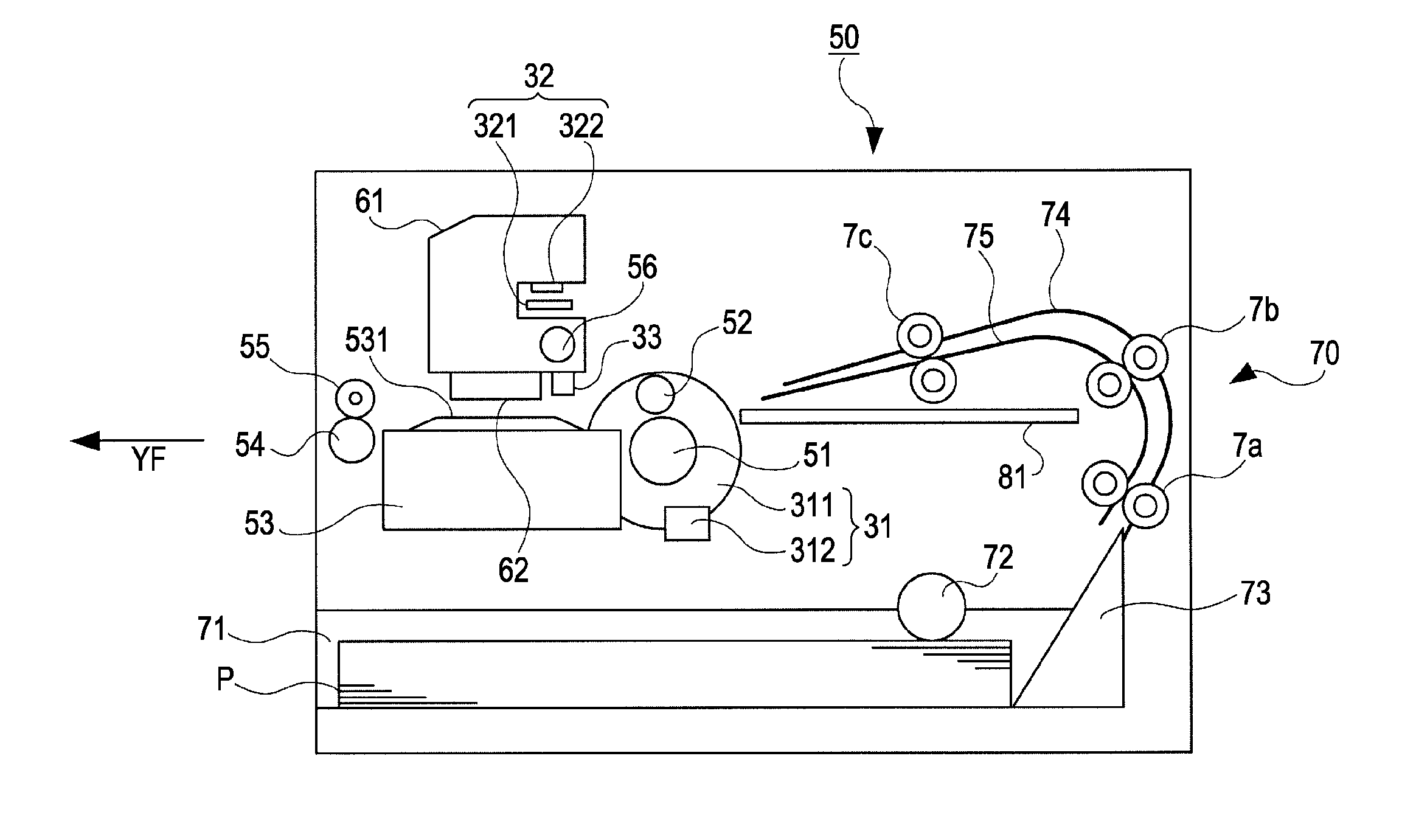
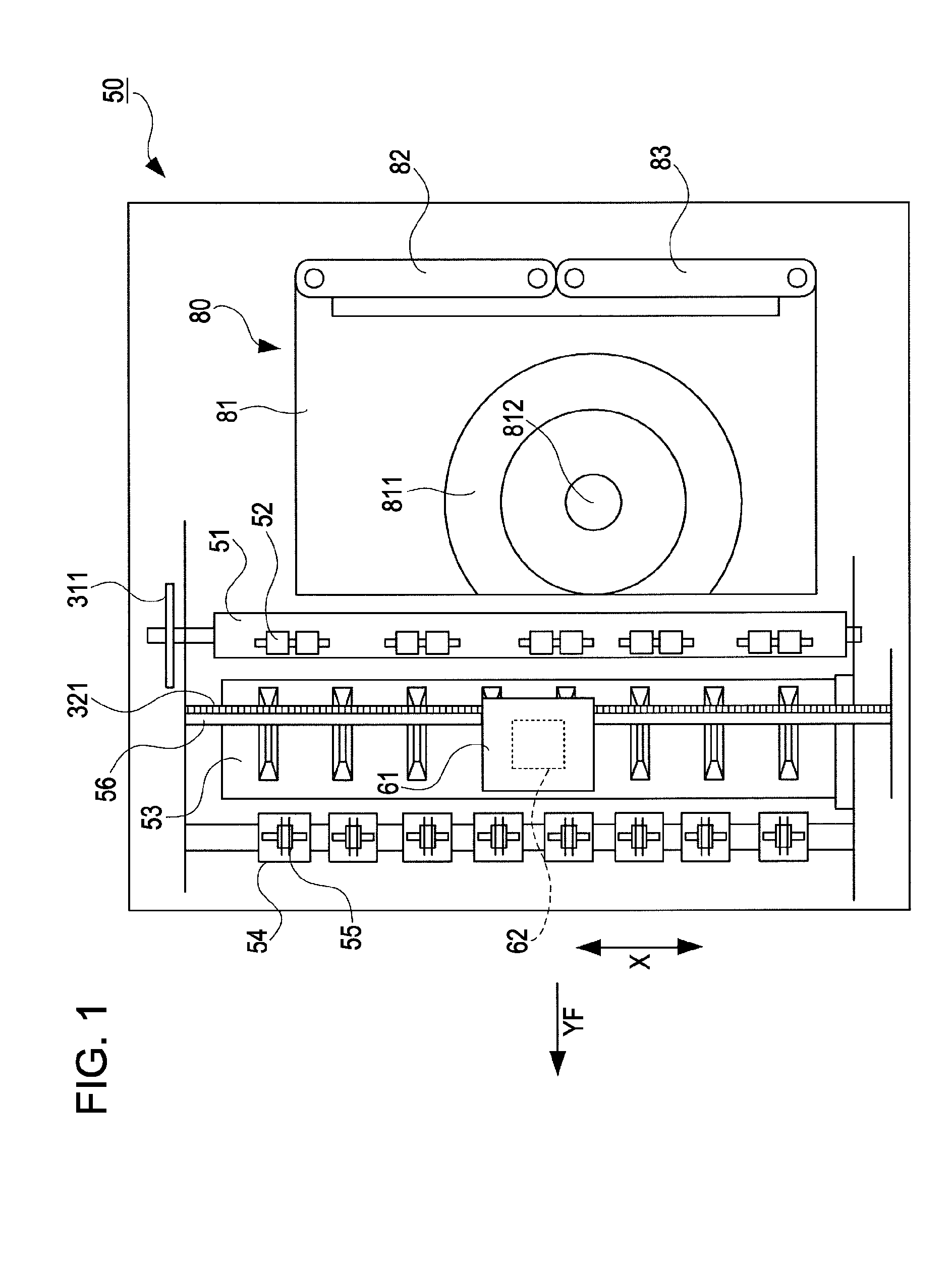
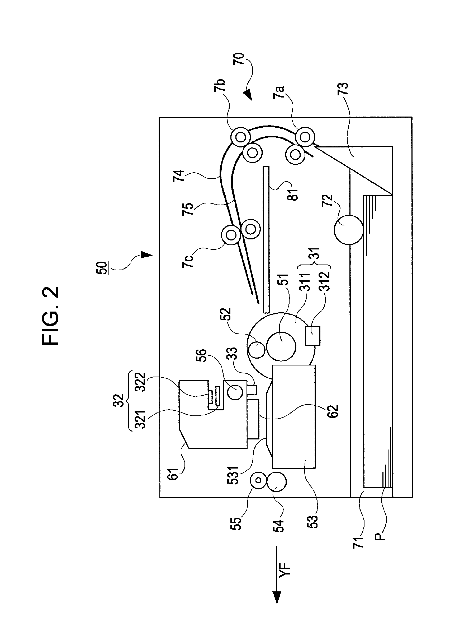
[0042]FIG. 1 is a plan view showing a main part of the ink jet printer 50. FIG. 2 is a side view showing the main part of the ink jet printer 50. FIG. 3 is a schematic block diagram showing the ink jet printer 50.

[0043]The ink jet printer 50 includes an automatic feeding device 70 which feeds a printing sheet P as “a printing medium” to the ink jet printer 50. In addition, the ink jet printer 50 includes a transport driving roller 51 and a transport driven roller 52 as “a transport device”. The ink jet printer 50 includes a printing head 62 as a member which performs a printing process by ejecting ink onto a printing surface of the printing sheet P support...

third embodiment

Ink Jet Printer of the Invention

[0086]The ink jet printer according to a third embodiment of the invention will be described with reference to FIGS. 12 to 14.

[0087]FIGS. 12 and 13 are perspective views showing the main part of the ink jet printer 50 according to the third embodiment. FIGS. 14A and 14B are enlarged perspective views showing a part provided with a first locking portion 88 and a part provided with a second locking portion 89.

[0088]The ink jet printer 50 according to the third embodiment is a printing apparatus having a structure in which the disc tray 81 is not provided and the disc tray 81 having the optical disc Di loaded thereon is manually inserted into the printing apparatus to be fed by the user. For this reason, the disc tray support device 80 is not provided. Further, in order to reliably and smoothly perform an operation in which the disc tray 81 is manually inserted into the printing apparatus by the user, a left guide portion 87L and a right guide portion 8...


PUM


Abstract

Provided is a printing apparatus for performing a printing process on a printing surface of a printing medium, the printing apparatus including: a transport device which transports a transport object having the printing medium loaded thereon in a predetermined transport direction; and a transport object locking portion which locks a movement of the transport object at a predetermined position on the upstream side or the downstream side of the transport direction, wherein a skewed posture of the transport object with respect to the transport direction is corrected in the state where the transport object is locked by the transport object locking portion.

Description

BACKGROUND[0001]1. Technical Field[0002]The present invention relates to a printing apparatus which performs a printing process on a printing surface of a printing medium and a method of correcting a skewed posture of a transport object in the printing apparatus.[0003]2. Related Art[0004]Among printing apparatuses such as ink jet printers, there is generally known a printing apparatus which transports a transport object such as an exclusive tray (hereinafter, simply referred to as “a disc tray”) having an optical disc such as a CD (compact disc) or a DVD (digital versatile disc) loaded thereon by using a transport device and performs a printing process on a label surface of the optical disc. In this kind of printing apparatus, when the printing process is performed in the state where a posture of the disc tray with respect to a transport direction of the transport device is skewed (hereinafter, simply referred to as “a skew”), a positional deviation occurs between the label surface ...

Claims


Application Information

Patent Timeline
IPC IPC(8): B41J29/38B41J2/01
CPCB41J3/4071B41J29/38B41J29/02B41J13/14
Inventor KOMURO, SHINTARO
Owner SEIKO EPSON CORP
Why Eureka
Try Eureka