Wearable image display device

a technology of image display device and wearable body, which is applied in the direction of optics, instruments, lenses, etc., can solve the problems of image display device drawbacks, achieve the effect of avoiding discontinuities in optical surfaces, and being economical to constru

Inactive Publication Date: 2010-02-11
YUNG MAN FAT
View PDF8 Cites 63 Cited by
  • Summary
  • Abstract
  • Description
  • Claims
  • Application Information

AI Technical Summary

Benefits of technology

[0023]This invention provides a device which is effective and efficient in operational use, which may be economically constructed and which avoids discontinuities in the optical surfaces of the device.

Problems solved by technology

However, this image display device has some drawbacks.

Method used


Image

  • Wearable image display device
  • Wearable image display device
  • Wearable image display device

Examples


Embodiment Construction

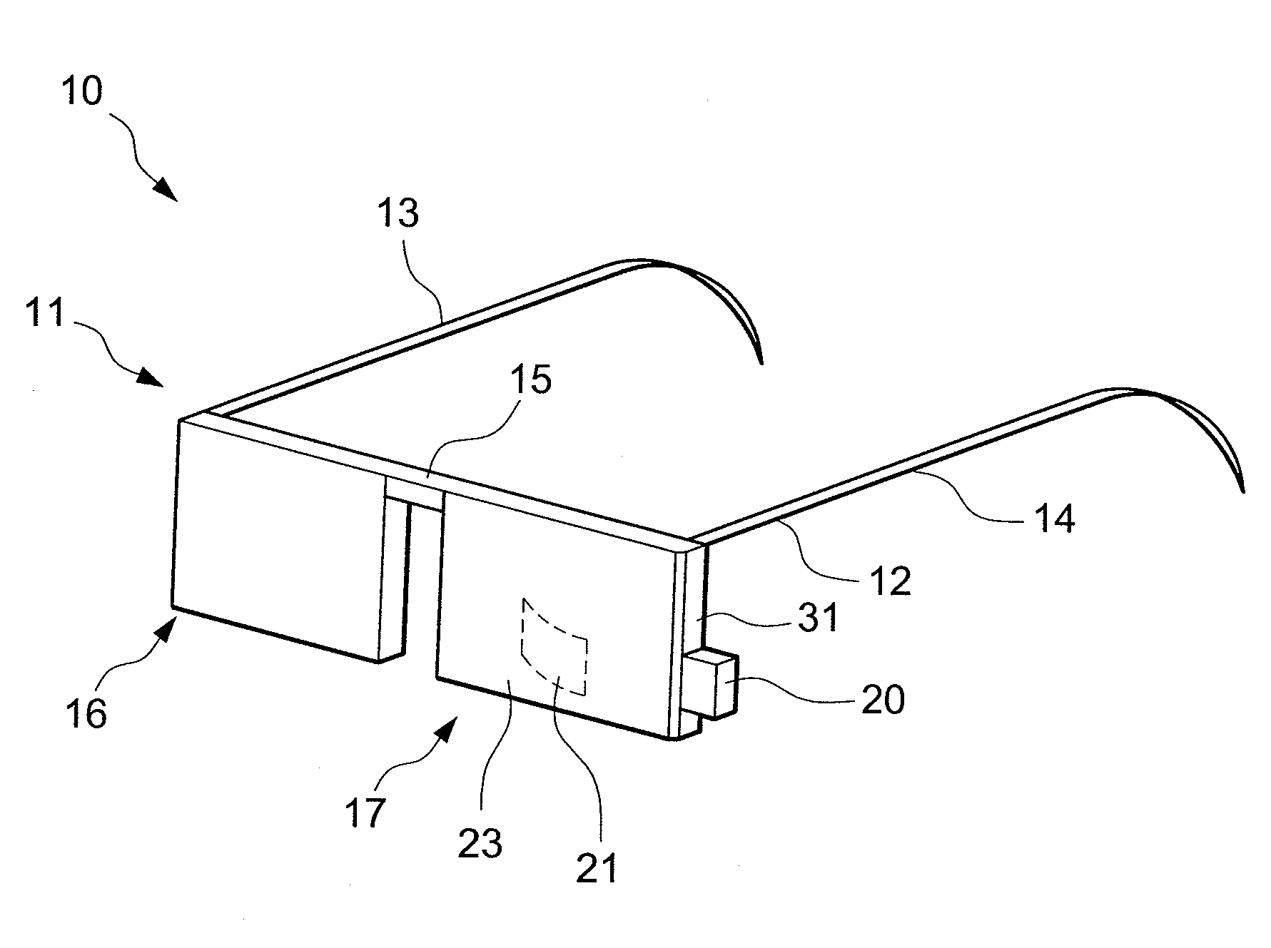
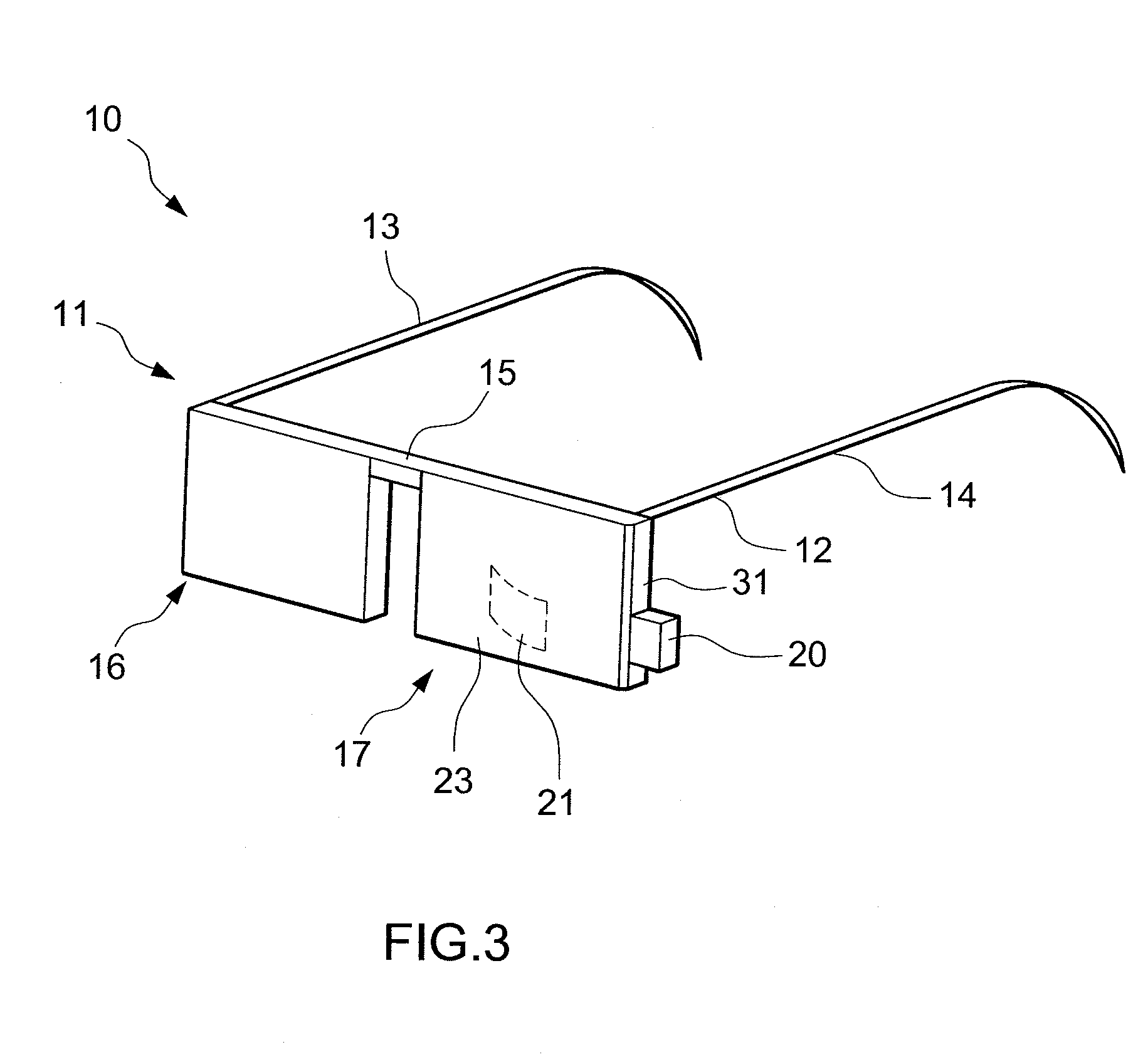
[0029]Referring to FIGS. 3 and 4, a wearable image display device 10 according to a preferred embodiment of the invention is provided as comprising a pair of spectacles 11 including a frame 12 having a pair of laterally spaced temples 13, 14, a bridge 15 and a pair of lenses 16, 17. The lenses 16, 17 may be either of suitable prescription or of non-corrective construction. Frame 12 including temples 13, 14 and bridge 15 are constructed and sized for mounting on the head of an individual wearer as is conventional, with the lenses being spaced from the wearer's eyes along a central axis 18 and defining an open eye cavity 19 therebetween. A battery powered microdisplay 20 is mounted to the lens 17 for continuously or selectively optically radiating its image into cavity 19. A partially transmissive reflector 21 within the lens 17 intercepts light radiated by the microdisplay 20 and to reflect light out of the lens 17 onto the wearer's eye 30.

[0030]The microdisplay 20 can be any electro...


PUM


Abstract

A wearable image display device for superimposing a virtual image into the wearer's field of vision includes a lens, for spectacles or the like, which includes inner and outer lens portions bonded together at complementary boundary surfaces of the lens portions. One of two opposing optical surfaces of the lens is located on each lens portion. Each boundary surface is disposed between the optical surfaces of the inner and outer lens portions to avoid discontinuities on the optical surfaces. A partially transmissive reflector is located on one of the boundary surfaces and a microdisplay radiates light internally through the lens between the optical surfaces of the inner and outer lens portions to strike the partially transmissive reflector and reflect the light out of the lens to a user's eye.

Description

TECHNICAL FIELD [0001]The present invention relates to a small image display device that can be used while worn on the head.BACKGROUND OF THE INVENTION [0002]Recently, small image display devices have been proposed that allow users to view both images and the surrounding environment by providing virtual images superimposed upon part of the field of vision.[0003]An image display device of this type is disclosed in, for example, U.S. Pat. No. 6,384,982. Eyeglasses include a composite lens positioned in the wearer's field of vision, the composite lens having a partially reflective internal interface. A miniature display, such as a backlit liquid crystal display (LCD) is mounted to a frame for holding the composite lens. The LCD projects light through an edge of the composite lens against an interface between two portions of the composite lens and the light is then reflected into the user's eyes to produce the image.[0004]The image display device of this type provides the capacity to se...

Claims


Application Information

Patent Timeline
Patent Type & Authority Applications(United States)
IPC IPC(8): G02B27/01
CPCG02B3/00G02B2027/012G02B27/0172
Inventor YUNG, MAN FAT
Owner YUNG MAN FAT
Why Eureka
Try Eureka