Motorized umbrella

a motorized umbrella and umbrella technology, applied in the field of umbrellas, can solve the problems of adding considerable complexity and cost to umbrellas, and reducing the working life so as to increase the working life, reduce the cost, and reduce the effect of threaded rods and nuts

Inactive Publication Date: 2009-07-21
CHIAPHUA COMPOPONENTS
View PDF19 Cites 23 Cited by
  • Summary
  • Abstract
  • Description
  • Claims
  • Application Information

AI Technical Summary

Benefits of technology

[0016]A first cushion is preferably fixed at the inner end of the support tube for abutting the yoke at the inner limit of travel of the sleeve and a second cushion fixed at outer end of the sleeve for abutting the crown at the outer limit of travel of the sleeve. Preferably the first cushion is in sliding contact with the sleeve and the second cushion is in sliding contact with the rod for preventing entry of foreign matter.
[0039]This invention provides umbrella which is effective and efficient in operational use, and which may be economically constructed. It provides a self-contained motorised umbrella capable of being used remotely from a power supply and the drive means is sealed to increase its working life and reduce the need for maintenance.

Problems solved by technology

A drawback with this design is the necessity to provide longitudinal openings in the pole for receiving fasteners connecting the internal nut to the external sleeve.
Such openings not only detract from the appearance of the umbrella but also permit the entry of foreign matter which is likely to degrade the performance and reduce the working life of the threaded rod and nut.
The flexible member connecting the shaft and sleeve, as well as the cooperating pulley necessary in this umbrella, add considerable complexity and cost to this umbrella.
Furthermore, particularly when the umbrella is placed in storage when not in use, it is disadvantageous that the overall length of the umbrella is extended when it is closed.

Method used


Image

  • Motorized umbrella
  • Motorized umbrella
  • Motorized umbrella

Examples


Embodiment Construction

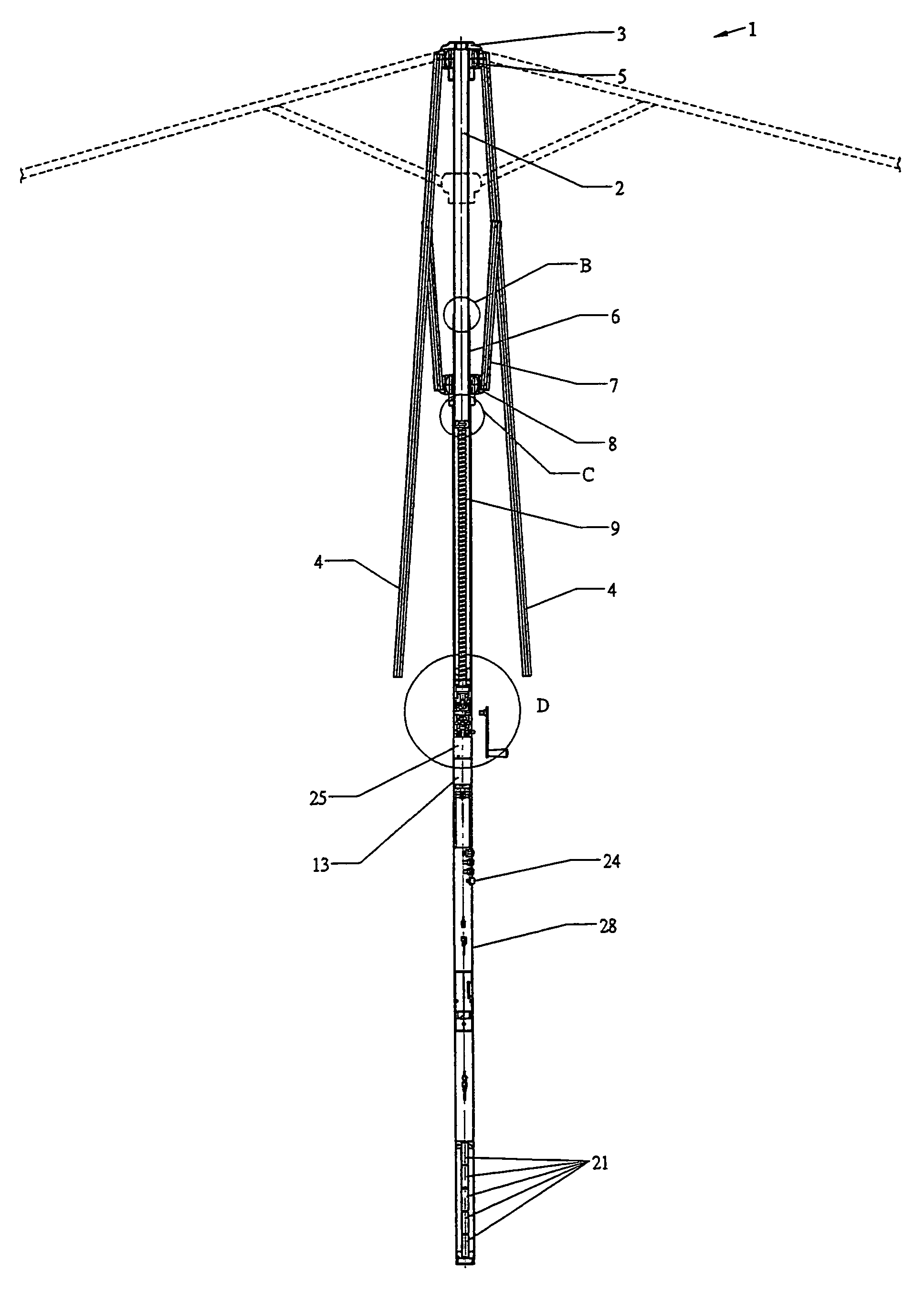
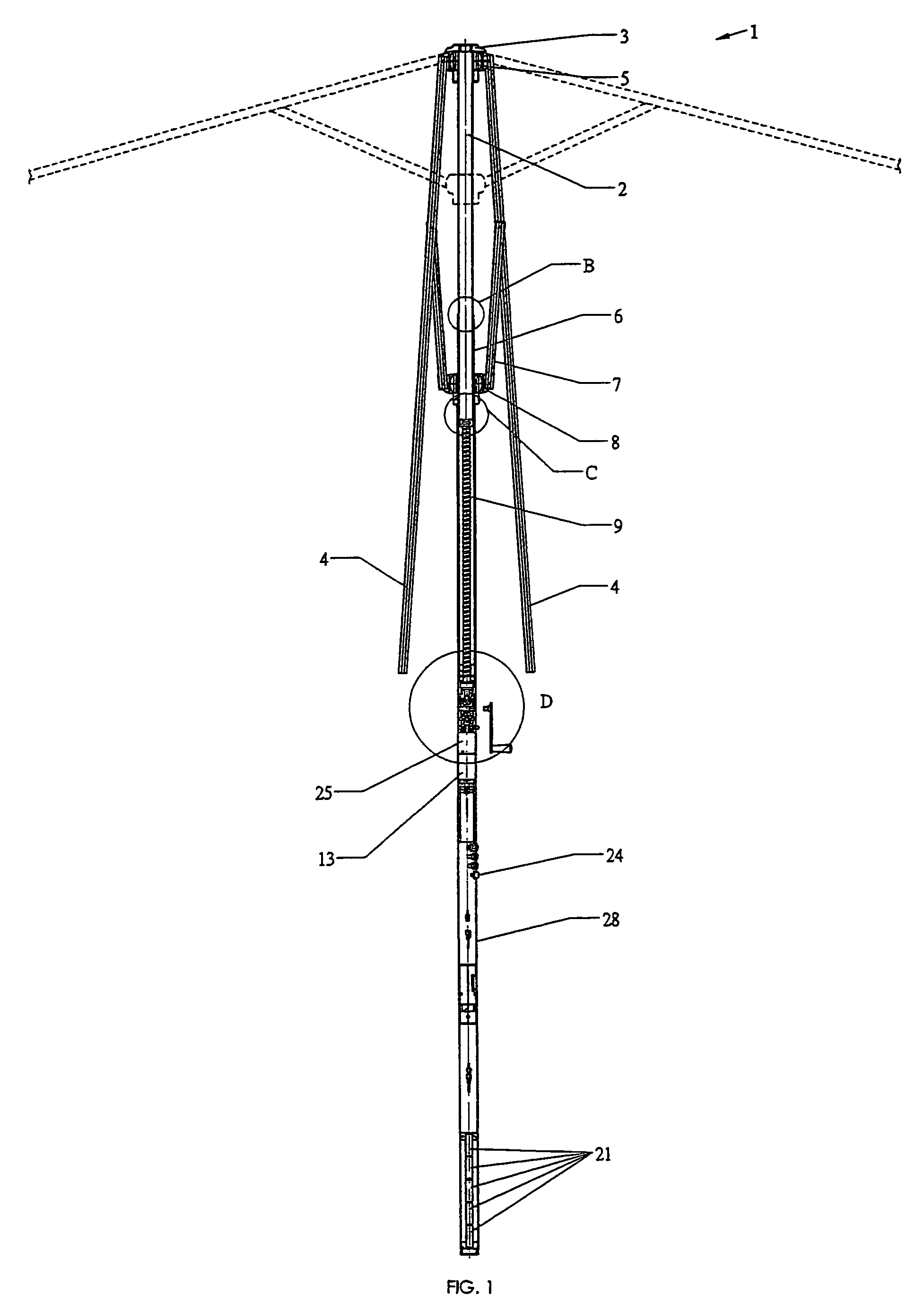
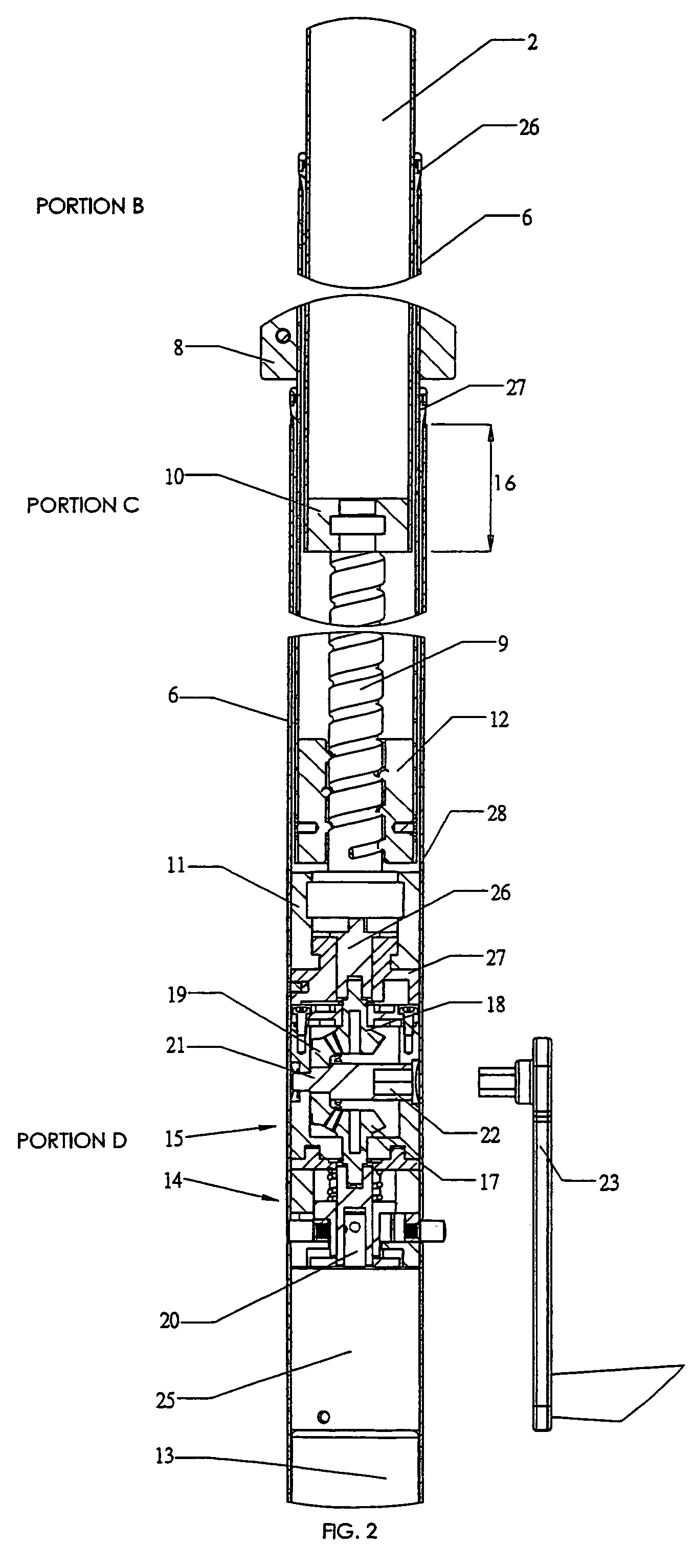
[0047]Referring to FIGS. 1 and 2, a motorised umbrella 1 includes an upright rod 2 having a crown 3 fixed at an outer end thereof. A plurality ribs 4 for supporting the umbrella canopy (not shown) are connected at one end to the crown 3 by pivots 5 to extend radially from the rod 2. A sleeve 6 is in external sliding relationship to the rod 2 received therein. The sleeve 6 is moveable relative to the rod 2 between the inner retracted position shown and an extended (upper) position.

[0048]Note that the terms “inner” and “outer” are used to describe relationships relative to both of the two longitudinally opposing ends of the central post assembly of the umbrella. The references in brackets relate to the upright orientation shown in FIGS. 1 and 2 and are added for clarity.

[0049]A plurality of struts 7 are pivotally connected between a yoke 8 fixed to the sleeve 6, each strut 7 being connected to an associated one of the ribs 4. When moving the sleeve 6 from the retracted position to the...


PUM


Abstract

Radially disposed ribs for supporting the canopy of an umbrella are pivotally connected by a crown mounted on the outer end of a rod. A sleeve is in external sliding relationship with the rod. Struts are pivotally connected to the sleeve, each strut being associated with one of the ribs for splaying the ribs and collapsing them inwardly. A support tube is connected by a coaxial shaft to the rod, and the sleeve is telescopically received in the support tube. The shaft is threaded and rotated by motor, opposing ends of the threaded shaft being supported for rotation in first and second journals fixed within the support tube and the rod, respectively. A threaded nut fixedly connected to the sleeve is engaged with the threaded shaft for moving the sleeve along the rod between extended and retracted positions.

Description

BACKGROUND OF THE INVENTION[0001]The present invention relates to umbrellas and particularly, but not exclusively, to umbrellas the opening and closing of which is motorised.[0002]A typical umbrella is constructed with a support pole carrying at its uppermost end a crown with radiating ribs pivotally connected thereto and a sleeve sliding over the pole with struts being interconnected between the sleeve and the ribs. Various motorised drive mechanisms have been provided to slide the sleeve along the pole in order to cause the struts to splay the ribs attached to the crown upwardly and outwardly.[0003]U.S. Pat. No. 6,543,464 describes an umbrella where the linear movement of the sleeve along the pole is driven by a threaded rod received within a tubular support pole and cooperating with a threaded nut to which the sleeve is fixed. A drawback with this design is the necessity to provide longitudinal openings in the pole for receiving fasteners connecting the internal nut to the extern...

Claims


Application Information

Patent Timeline
Patent Type & Authority Patents(United States)
IPC IPC(8): A45B17/00
CPCA45B25/143
Inventor CHAN, PING CHIU
Owner CHIAPHUA COMPOPONENTS
Why Eureka
Try Eureka