
Knee joint bandage

a knee joint and bandage technology, applied in the field of knee joint bandage, can solve the problems of dislocation of the kneecap from its normal position, and achieve the effect of counteracting the lifting of the kneecap and improving the conventional knee joint bandag

Active Publication Date: 2010-02-11
BAUERFEIND GMBH & CO
View PDF10 Cites 30 Cited by
  • Summary
  • Abstract
  • Description
  • Claims
  • Application Information

AI Technical Summary

Benefits of technology

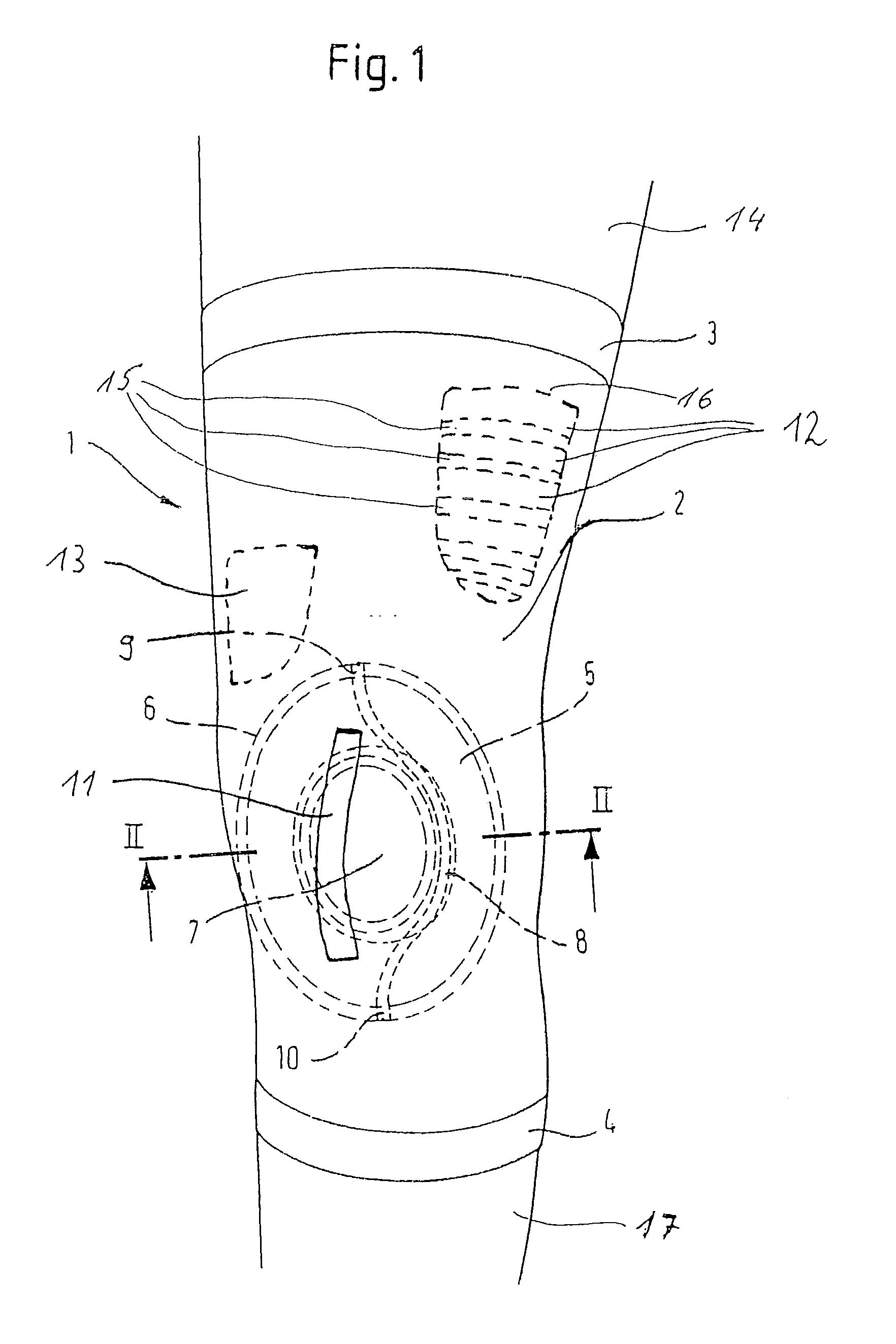
[0006]It is the object of an embodiment of the invention to improve the conventional knee joint bandage such that while retaining the desired effect of the tensioning member, any wiggle room of the kneecap away from the knee joint is prevented. According to the embodiment of the invention, this is done by providing the bandage in the region of the kneecap with a flexible tensioning band, which in its peripheral region relative to the tensioning member partially covers the kneecap, with the tensioning band extending substantially in the direction between the kneecap poles such that it counteracts a lifting of the kneecap.
[0007]As a result of the tensioning band extending across the region of the kneecap partially covering the kneecap in its peripheral area relative to the tensioning member, instant pressure is exerted on the affected region of the kneecap as soon as the kneecap shows any tendency of lifting off the joint. In this instance, the non-elastic tensioning band acts, in a manner of speaking, as a movement limiter, for the corresponding side of the kneecap so that laterally, it can be marginally displaced from the tensioning member but is prevented by the tensioning band from thereby lifting off the knee joint. This is a technically simple but functionally important additional structural design of the knee joint bandage, which merely in the region of the kneecap requires the addition of the aforementioned tensioning band.
[0008]The previously described knee joint bandage can be combined in a beneficial manner with a femoral bandage, which adjoins the knee joint bandage, and, in a manner of speaking, is a continuation thereof, wherein a pelotte is inserted into the femoral bandage extending in the longitudinal direction of the bandage and featuring transversal ribs, the ribs being separated by likewise transversal notches. With a pelotte such as this, by pressing the corresponding bandage on a muscle located therebelow, a relaxing of said muscle can be achieved, which is of particular importance if the muscle is responsible for a dislocation of the kneecap. In other words, the pelotte with its transversal ribs ensures that by relaxing the muscle in question, the strength for moving the kneecap is decreased.

Problems solved by technology

In a worst case scenario, this can result in the dislocation of the kneecap from its normal position.

Method used


Image

  • Knee joint bandage
  • Knee joint bandage
  • Knee joint bandage

Examples


Embodiment Construction

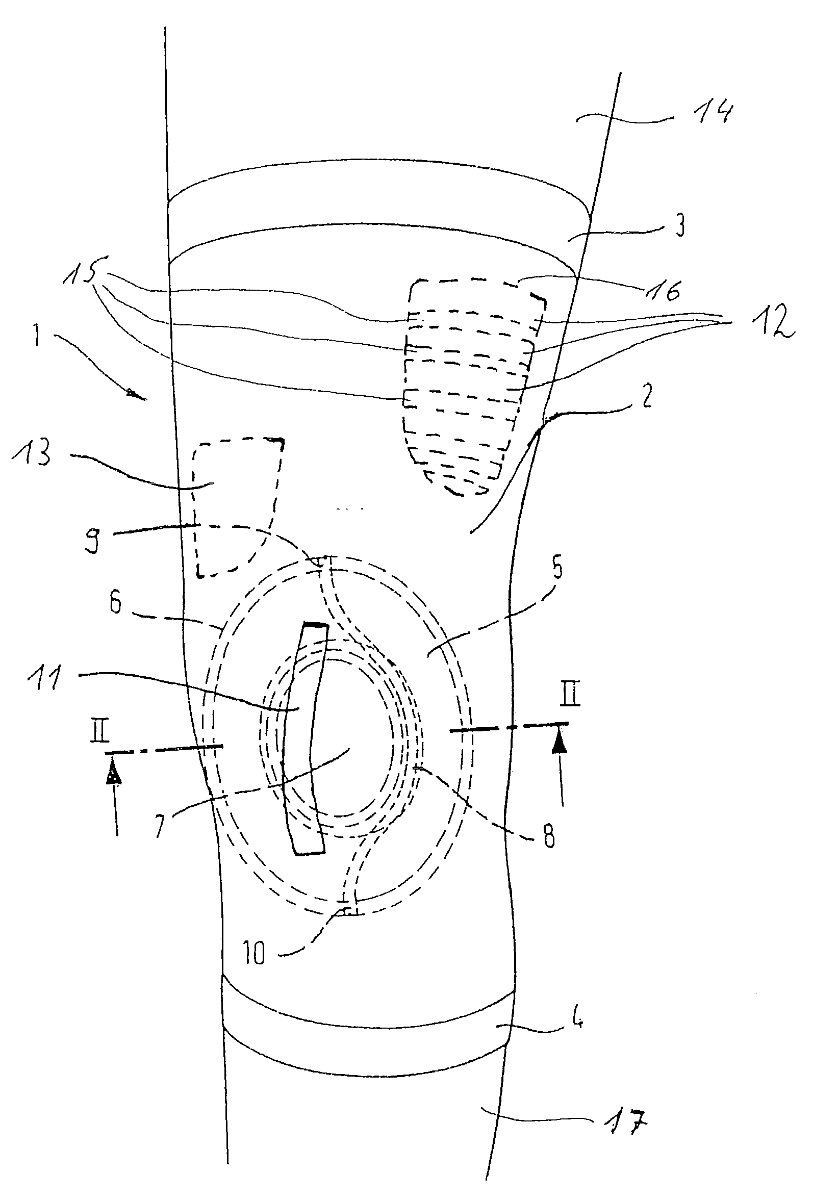
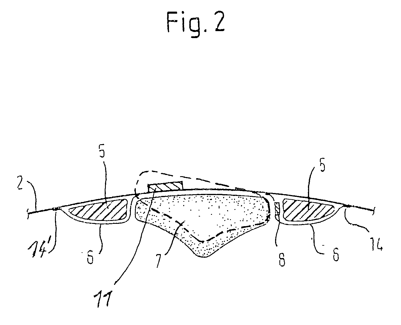
[0013]FIG. 1 illustrates bandage 1, which extends from thigh 14 to lower leg 17 and is made of an elastic textile material 2. To facilitate its application and removal, longitudinal strips 3 and 4 are attached to bandage 1, the strips being made of longitudinally elastic material forming a non-fraying edge of bandage 1. In the region of the knee joint, bandage 1 is of a special structural design, which counteracts a lateral displacement of kneecap 7 during bending of the knee. For this purpose, bandage 1 has a profiled insert 5 having a recess encompassing the kneecap 7. Enclosed in the overlay 6 over the profiled insert 5 is the flexible but non-expandable tensioning member 8, which at its ends 9 and 10 is firmly attached to the profiled insert 5. If the leg illustrated in a straightened position is bent, the bandage 1 expands in the region of the knee joint causing the ends 9 and 10 of tensioning member 8 to separate from one another, and as a result, the tensioning member 8 is di...


PUM


Abstract

A knee joint bandage made of elastic textile material having a profiled insert encompassing the kneecap in a recess, the insert being covered by an overlay fastened to the textile material. Within the profile insert is a flexible, non-expandable tensioning member for connecting the regions of the kneecap poles on the fibula side in an arc around the kneecap wherein the distance between these regions increases during bending of the knee joint, the distance of the arc from the connecting line of the knee poles in decreased, and the tensioning member presses on the adjacent side of the kneecap, displacing the same medially and centering it. The bandage is provided with a flexible tensioning band, which partially covers the kneecap in its peripheral area relative to the tensioning member, the tensioning band substantially extends in the direction between the kneecap poles such that it counteracts a lifting of the kneecap.

Description

CROSS-REFERENCE TO RELATED APPLICATIONS[0001]The present application claims priority under 35 USC 119 to PCT Patent Application No. EP2007 / 011218 filed on Dec. 19, 2007 which claims priority to German Patent Application No. 10 2006 061 060.1 filed on Dec. 22, 2006 the entire contents of which are hereby incorporated by reference.BACKGROUND OF THE INVENTION[0002]1. Field of the Invention[0003]The invention relates to a knee joint bandage made of elastic textile material, the bandage being provided with a profiled insert encompassing the kneecap in a recess, the insert being covered by an overlay, which is fastened to the textile material and is made of identical of similar textile material. Arranged with the profiled insert is a flexible, non-expandable tensioning member connecting the regions of the kneecap poles on the fibula side in an arc around the kneecap such that as the distance between these regions increases during bending of the knee joint, the distance of the arc from the...

Claims


Application Information

Patent Timeline
IPC IPC(8): A61F5/00
CPCA61F5/0106A61F2005/0176A61F13/061A61F5/30
Inventor BAUERFEIND, HANS B.KRAUSE, WOLFGANGHESS, HEINRICHSCHEUERMANN, RAINER
Owner BAUERFEIND GMBH & CO
Learn More