Low profile transcatheter heart valve

a low-profile, heart valve technology, applied in the direction of venous valves, prostheses, catheters, etc., can solve the problems of significant heart failure, high morbidity and mortality rate of chronically ill patients, and patients who cannot survive the surgical procedure or di

Active Publication Date: 2010-02-11
EDWARDS LIFESCIENCES CORP
View PDF5 Cites 446 Cited by
  • Summary
  • Abstract
  • Description
  • Claims
  • Application Information

AI Technical Summary

Benefits of technology

[0014]In another representative embodiment, a method is disclosed for crimping an implantable prosthetic valve having a frame and leaflets supported by the frame. The method comprises placing the valve in the crimping aperture of a crimping device such that a compressible material is disposed between the crimping jaws of the crimping device and the frame of the valve. Pressure is applied against the compressible material and the valve with the crimping jaws to radially crimp the valve to a smaller profile and compress the compressible material against the valve such that the compressible material extends into open cells of the frame and pushes the leaflets away from the inside of the frame.
[0015]The foregoing and other features and advantages of the invention will become more apparent from the following detailed description, which proceeds with reference to the accompanying figures.

Problems solved by technology

These valvular diseases can result in significant malfunctioning of the heart and ultimately require replacement of the native valve with an artificial valve.
The problem with surgical therapy is the significant insult it imposes on these chronically ill patients with high morbidity and mortality rates associated with surgical repair.
Because of the trauma associated with the procedure and the attendant duration of extracorporeal blood circulation, some patients do not survive the surgical procedure or die shortly thereafter.
It is well known that the risk to the patient increases with the amount of time required on extracorporeal circulation.
Due to these risks, a substantial number of patients with defective valves are deemed inoperable because their condition is too frail to withstand the procedure.
Because of the drawbacks associated with conventional open-heart surgery, percutaneous and minimally-invasive surgical approaches are garnering intense attention.

Method used


Image

  • Low profile transcatheter heart valve
  • Low profile transcatheter heart valve
  • Low profile transcatheter heart valve

Examples


Embodiment Construction

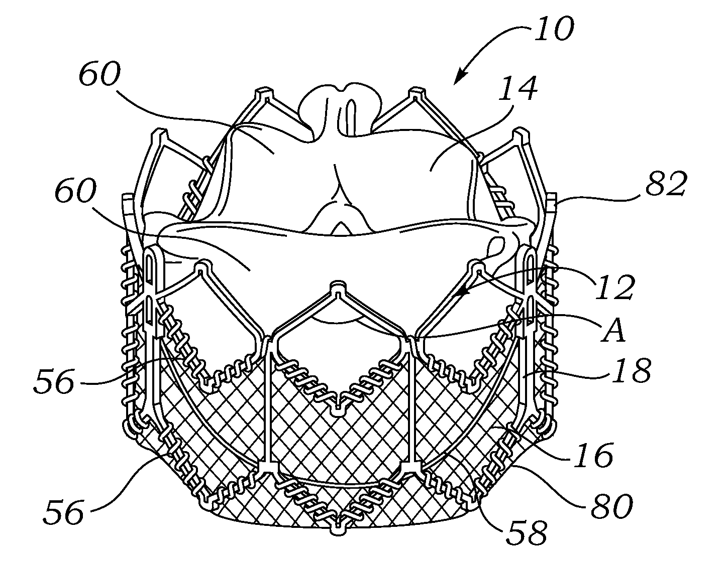
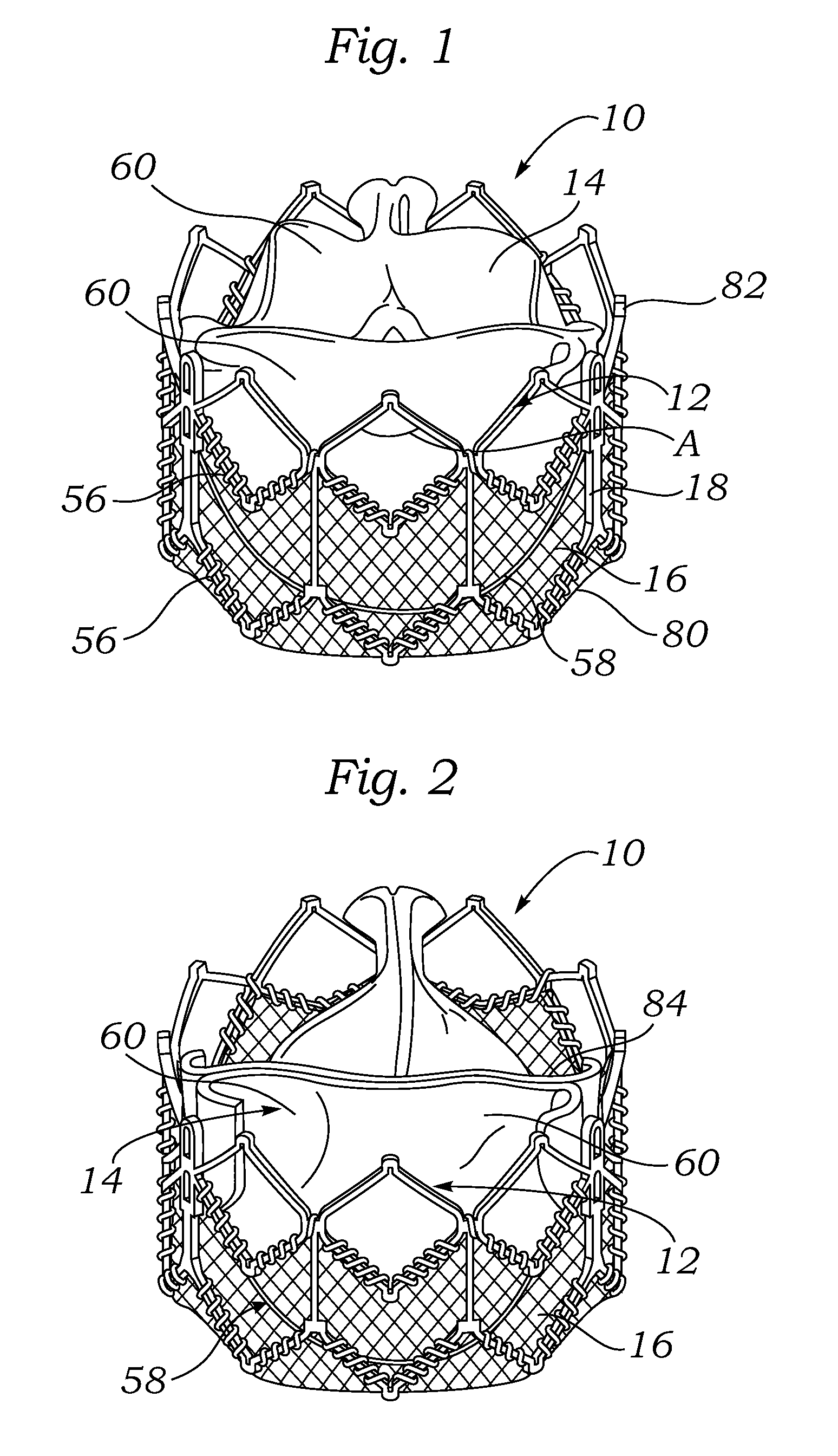
[0047]FIGS. 1 and 2 illustrate an implantable prosthetic valve 10, according to one embodiment. Valve 10 in the illustrated embodiment generally comprises a frame, or stent, 12, a leaflet structure 14 supported by the frame, and a skirt 16 secured to the outer surface of the leaflet structure. Valve 10 typically is implanted in the annulus of the native aortic valve but also can be adapted to be implanted in other native valves of the heart or in various other ducts or orifices of the body. Valve 10 has a “lower” end 80 and an “upper” end 82. In the context of the present application, the terms “lower” and “upper” are used interchangeably with the terms “inflow” and “outflow”, respectively. Thus, for example, the lower end 80 of the valve is its inflow end and the upper end 82 of the valve is its outflow end.

[0048]Valve 10 and frame 12 are configured to be radially collapsible to a collapsed or crimped state for introduction into the body on a delivery catheter and radially expandab...


PUM

PropertyMeasurementUnit
angleaaaaaaaaaa
angleaaaaaaaaaa
angleaaaaaaaaaa

Abstract

An implantable prosthetic valve, according to one embodiment, comprises a frame, a leaflet structure, and a skirt member. The frame can have a plurality of axial struts interconnected by a plurality of circumferential struts. The leaflet structure comprises a plurality of leaflets (e.g., three leaflets arrange to form a tricuspid valve). The leaflet structure has a scalloped lower edge portion secured to the frame. The skirt member can be disposed between the leaflet structure and the frame.

Description

CROSS REFERENCE TO RELATED APPLICATION[0001]This application claims the benefit of U.S. Provisional Patent Application No. 61 / 059,656, filed Jun. 6, 2008, which is incorporated herein by reference.FIELD[0002]The present disclosure relates to implantable devices and, more particularly, to valve prosthetics for implantation into body ducts, such as native heart valve annuluses.DESCRIPTION OF THE RELATED ART[0003]The human heart can suffer from various valvular diseases. These valvular diseases can result in significant malfunctioning of the heart and ultimately require replacement of the native valve with an artificial valve. There are a number of known artificial valves and a number of known methods of implanting these artificial valves in humans.[0004]Various surgical techniques may be used to repair a diseased or damaged valve. In a valve replacement operation, the damaged leaflets are excised and the annulus sculpted to receive a replacement valve. Due to aortic stenosis and other...

Claims


Application Information

Patent Timeline
Patent Type & Authority Applications(United States)
IPC IPC(8): A61F2/24
CPCA61F2/2412A61F2/2418A61F2/2433A61F2230/0054A61F2220/0075A61F2/2475A61F2220/005A61F2002/9522A61F2/95Y10T29/49863A61F2220/0033A61F2/9522B05B1/185E03C1/025E03C1/066
Inventor HARITON, ILIABENICHOU, NETANELNITZAN, YAACOVFELSEN, BELLANGUYEN-THIEN-NHOH, DIANAKHANNA, RAJESHNGUYEN, SON V.LEVI, TAMIRPELLED, ITAI
Owner EDWARDS LIFESCIENCES CORP
Why Eureka
Try Eureka