Rollover wash unit and method for mounting a rollover wash unit

a technology for washing units and rollovers, which is applied in the direction of vehicle maintenance, domestic objects, applications, etc., can solve the problems of affecting the service life of the rollover wash unit, the inability to transport special trucks, and the associated cost of reinstallation on the vehicle wash system, so as to achieve efficient and space-saving transportation, simple and fast assembly, and efficient and space-saving

Inactive Publication Date: 2010-02-18
WASHTEC HLDG
View PDF0 Cites 2 Cited by
  • Summary
  • Abstract
  • Description
  • Claims
  • Application Information

AI Technical Summary

Benefits of technology

[0006]The present invention therefore is based on the objective of making available a rollover wash unit and a method for assembling a rollover wash unit that eliminate

Problems solved by technology

However, this advantage of the quickest possible start-up of the rollover wash unit at the operator of the vehicle wash system is associated with the disadvantage that rollover wash units can only be transported with special trucks due to the considerable width, height, and weight of the rollover wash unit.
Furthermore, the space between the lateral parts and the portal traverse remains largely unused during the transport due to the portal shape of the rollover wash unit.
Consequently, the traveling legs of the lateral parts of the rollover wash unit are removed prior to the transport, wherein their in situ reinstallation on the vehicle wash system is associated with significant expenditures.
The size of a completely assembled rollover wash unit frequently also creates

Method used


Image

  • Rollover wash unit and method for mounting a rollover wash unit
  • Rollover wash unit and method for mounting a rollover wash unit
  • Rollover wash unit and method for mounting a rollover wash unit

Examples


Embodiment Construction

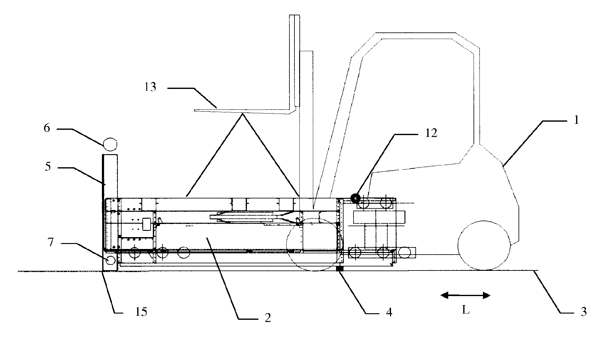
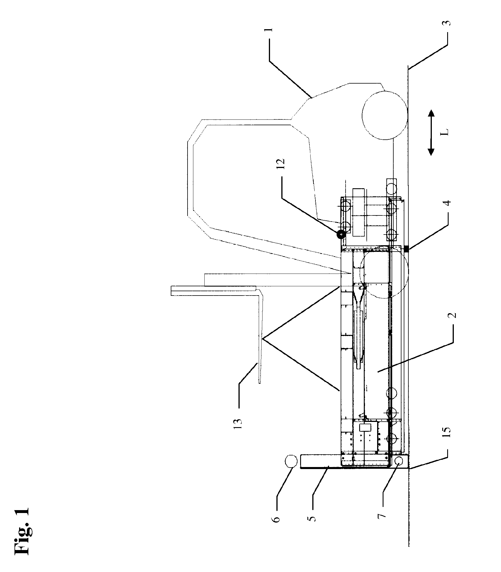
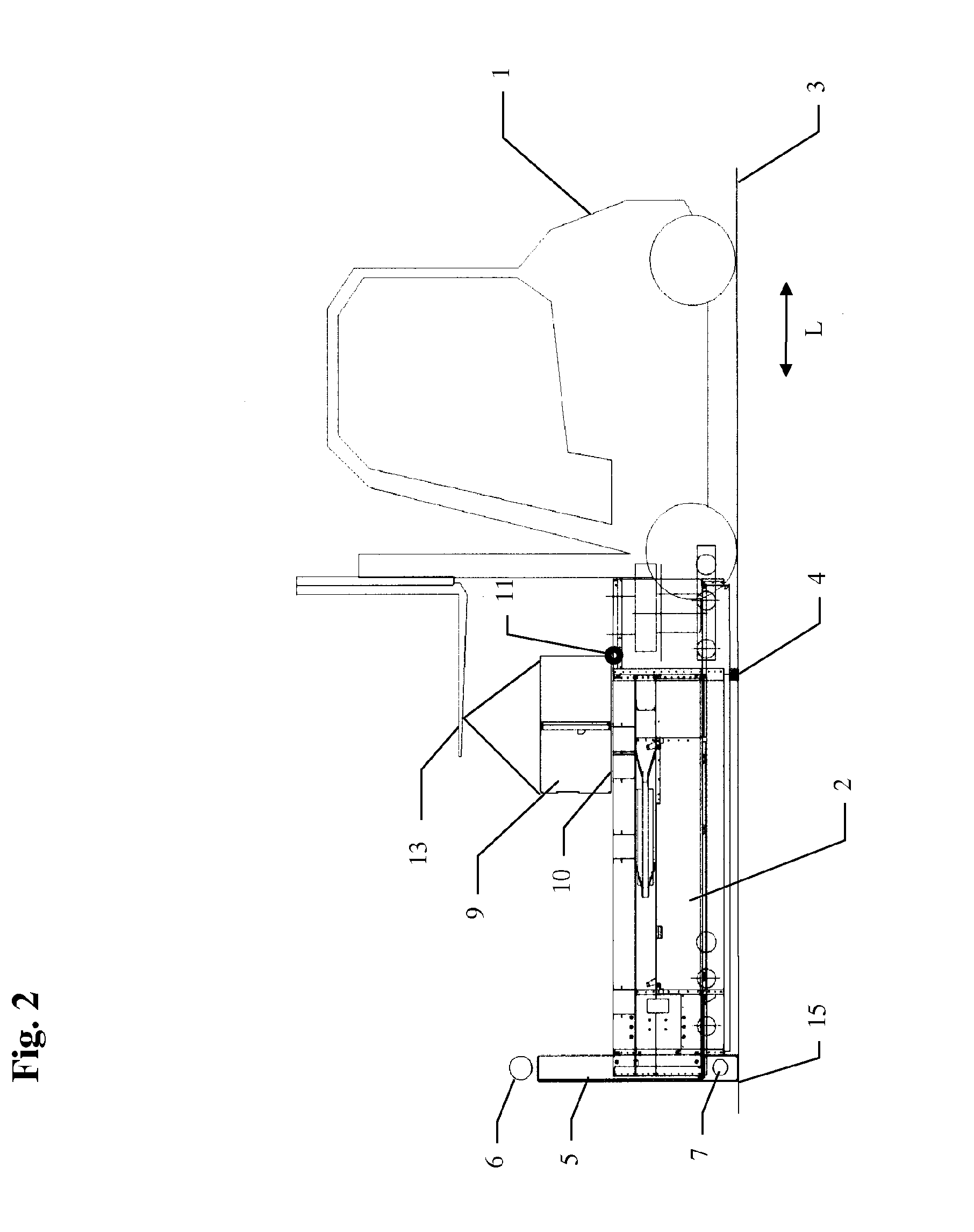
[0020]FIGS. 1-7 show the installation of a rollover wash unit in a washing bay from the delivery of the individual components up to the completed assembly of rollover wash unit. In FIG. 1, a conventional forklift 1 transports a left lateral element 2 of a rollover wash unit into the washing bay and places this lateral element onto a support beam 4 on the washing bay floor 3. The lateral element 2 consequently is in a position in which it is turned by 90° referred to its final position (see FIG. 7). A traveling leg 5 is rigidly arranged on the lateral element 2, namely at the left end in FIG. 1, and features rollers 6, 7 that serve for displacing the rollover wash unit in the longitudinal or washing direction L within a rail arrangement that is not illustrated in the figures in its completely assembled state. The left lateral element 2 is positioned on the floor 3 in such a way that the rollers 6, 7 engage with a left rail of the rail arrangement as easily as possible during the asse...


PUM


Abstract

The invention relates to a rollover wash unit for a vehicle wash system, comprising a traverse (9) and two lateral parts (2, 8) which are permanently connected to the traverse (9) once the rollover wash unit is mounted. The invention also relates to a method for mounting said rollover wash unit. The aim of the invention is to allows an efficient and space-saving transport and tan efficient, simple and fast mounting of the rollover wash unit in situ. For this purpose, the traverse (9) and the lateral parts (2, 8) are rotatably interconnected via at least one articulated connection (11, 12) for mounting the rollover wash unit, said connection having a rotational axis that extends substantially perpendicular to the lateral parts (2, 8) and along the traverse (9). The method according to the invention comprises the following steps: positioning the lateral parts (2, 8) and the traverse (9) in a mounting position in relation to each other (FIGS. 1 to 4), establishing at least one articulated connection (11, 12) between the traverse (9) and the lateral parts (2, 8) so that the lateral parts (2, 8) can be rotated in relation to the traverse (9), displacing the traverse (9) from the mounting position (FIGS. 1 to 4) to a final position (FIG. 7), the lateral parts (2, 8) being displaced from the mounting position (FIGS. 1 to 4) to the final position (FIG. 7) about a rotation axis of the articulated connection which axis extends substantially perpendicular to the lateral parts (2, 8) and along the traverse (8), permanently connecting the traverse (9) to the lateral parts (2, 8) so that no rotation of the lateral parts (2, 8) in relation to the traverse (9) is possible.

Description

FIELD OF THE INVENTION[0001]The invention pertains to a rollover wash unit for a vehicle wash system, as well as to a method for assembling a rollover wash unit.BACKGROUND OF THE INVENTION[0002]Manufacturers of vehicle wash systems usually deliver rollover wash units for vehicle wash systems to the operators of the vehicle wash systems in the completely assembled state. This makes it possible to start up the vehicle wash system at the intended location as quickly as possible. However, this advantage of the quickest possible start-up of the rollover wash unit at the operator of the vehicle wash system is associated with the disadvantage that rollover wash units can only be transported with special trucks due to the considerable width, height, and weight of the rollover wash unit. Furthermore, the space between the lateral parts and the portal traverse remains largely unused during the transport due to the portal shape of the rollover wash unit. In larger rollover wash units, e.g., fo...

Claims


Application Information

Patent Timeline
IPC IPC(8): B60S3/00B23P17/04
CPCB60S3/00B60S3/06Y10T29/49623Y10T29/49627Y10T29/49826Y10T29/49625
Inventor WIMMER, GEORGHIRSCHMANN, RUDIGERHENNING, ROHNE
Owner WASHTEC HLDG
Why Eureka
Try Eureka