Supercharge Your Innovation With Domain-Expert AI Agents!

Solenoid valve having a two piece moving valve element

a technology of moving valve element and solenoid valve, which is applied in the direction of lift valve, water supply installation, gas/liquid distribution and storage, etc., can solve the problems of balanced valves having a significant seal, prone to leakage or preventing valve opening,

Active Publication Date: 2010-02-18
IMI WEBBER
View PDF13 Cites 3 Cited by
  • Summary
  • Abstract
  • Description
  • Claims
  • Application Information

AI Technical Summary

Benefits of technology

"The invention is a solenoid valve that uses a balanced armature and a seal to prevent leakage or prevent the valve from opening too much. The valve has a main spring and a return spring that hold the armature in place. When the coil is not energized, the armature moves a short distance before contacting the seat housing. The valve has a small gap between the seat and the orifice to prevent leakage or high pressure load hysteresis. The invention allows for a smaller coil or lower power requirements for a given size valve. The operating sequence of the valve is also described."

Problems solved by technology

Fluid pressure acts over the orifice area either against or with the spring load, giving a tendency either to leak or prevent opening of the valve.
Balanced valves may have a significant seal frictional force that the valve needs to overcome to operate.

Method used


Image

  • Solenoid valve having a two piece moving valve element
  • Solenoid valve having a two piece moving valve element

Examples


Embodiment Construction

[0003]FIG. 1 and the following description depict specific examples to teach those skilled in the art how to make and use the best mode of the invention. For the purpose of teaching inventive principles, some conventional aspects have been simplified or omitted. Those skilled in the art will appreciate variations from these examples that fall within the scope of the invention. Those skilled in the art will appreciate that the features described below can be combined in various ways to form multiple variations of the invention. As a result, the invention is not limited to the specific examples described below, but only by the claims and their equivalents.

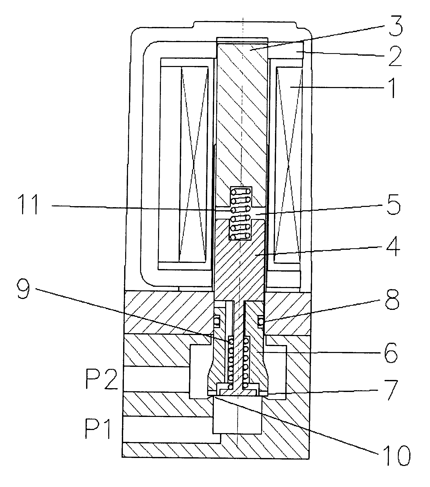
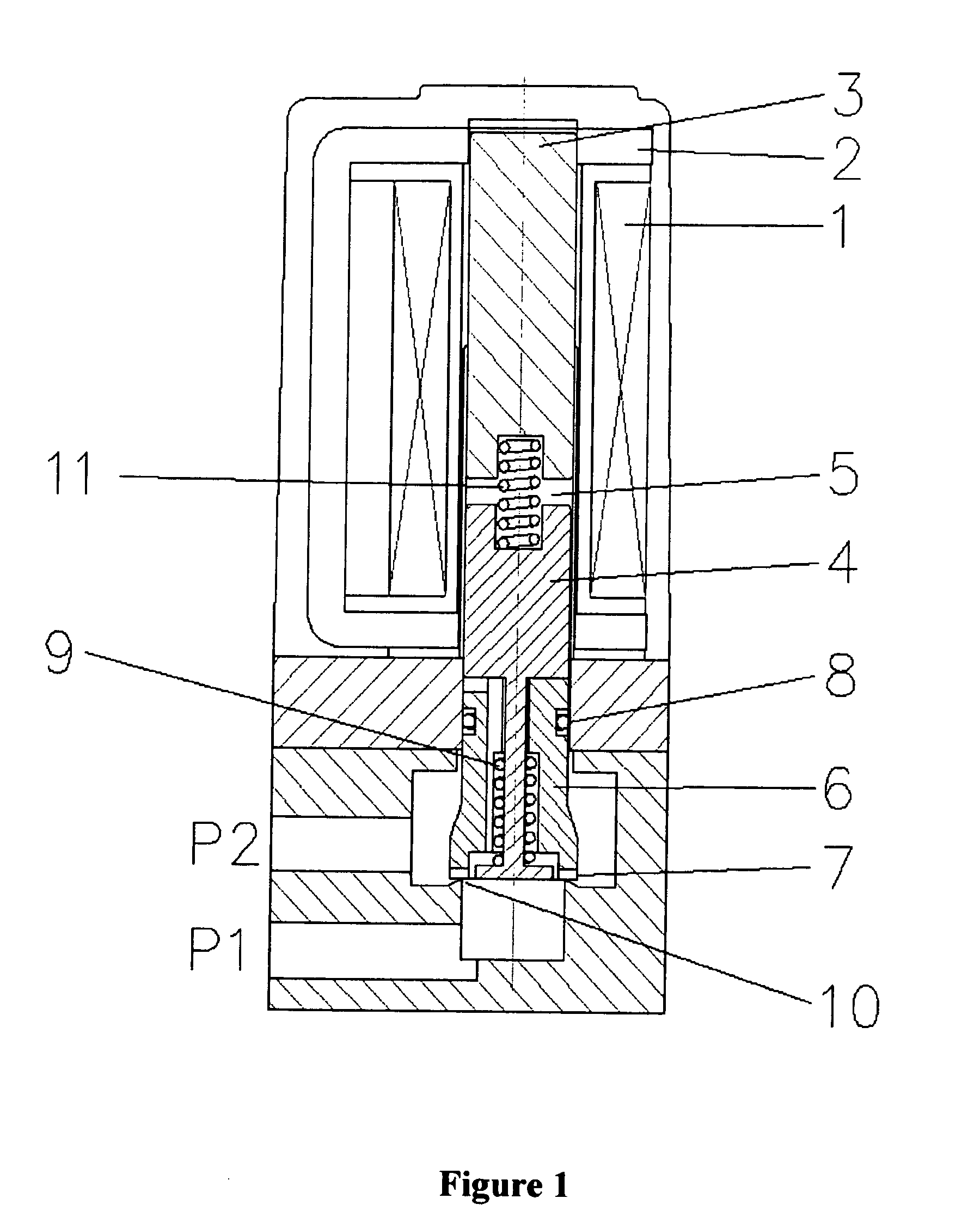
[0004]FIG. 1 is a sectional view of a solenoid valve in an example embodiment of the invention. Solenoid valve comprises a solenoid coil 1, an iron circuit 2, a fixed stem 3, a moving armature 4, a seat housing 6, a seat 7, a seal 8, a return spring 9, an orifice 10, and a main spring 11. In some embodiments of the invention the seat...


PUM


Abstract

A system and method for operating a solenoid valve is disclosed. The solenoid valve is operated by moving a first valve element (4) with respect to a second valve element (6, 7) a first distance. And then pulling the second valve element (6, 7) with the first valve element (4) a second distance where the second valve element (6, 7) moves against resistance from a seal (8) and where the movement of the second valve element (6, 7) opens a gap with respect to an orifice (10). The second element (6, 7) then moves a third distance under spring load to open an increased gap with respect to the orifice (10).

Description

BACKGROUND OF THE INVENTION[0001]Typical direct acting solenoid valves employ an armature containing a seal which is held against an orifice by a spring. Fluid pressure acts over the orifice area either against or with the spring load, giving a tendency either to leak or prevent opening of the valve. Some solenoid valves employ “balanced” armatures where the pressure across the orifice is counteracted by pressure across a seal of the same effective diameter as the orifice. This results in a significantly reduced load across the armature, particularly at higher pressure differentials. Balanced valves may have a significant seal frictional force that the valve needs to overcome to operate. The frictional forces typically increase with increasing pressure differential between the ports of the valve and with increasing seal diameter.BRIEF DESCRIPTION OF THE DRAWINGS [0002]FIG. 1 is a sectional view of a solenoid valve in an example embodiment of the invention.DETAILED DESCRIPTION OF THE...

Claims


Application Information

Patent Timeline
Patent Type & Authority Applications(United States)
IPC IPC(8): F15D1/00F16K31/02
CPCF16K1/54F16K39/02F16K31/10F16K31/0655Y10T137/0318
Inventor SCUDAMORE, GERALDBARNISH, CAINELLISON, PAUL
Owner IMI WEBBER
Features
  • R&D
  • Intellectual Property
  • Life Sciences
  • Materials
  • Tech Scout
  • Unparalleled Data Quality
  • Higher Quality Content
  • 60% Fewer Hallucinations
Learn More