Heat exchanger, use, and manufacturing process for a heat exchanger

Active Publication Date: 2010-02-18
BEHR GMBH & CO KG
View PDF13 Cites 21 Cited by
  • Summary
  • Abstract
  • Description
  • Claims
  • Application Information

AI Technical Summary

Benefits of technology

[0013]It is therefore an object of the present invention to provide a heat exchanger, in which the durability is improved and a fabrication process is designed more secure and / or simpler. It is also an object of the invention to provide a heat exchanger in which the collar of a passage creates improved conditions for a process-secure and automated fabrication by means of an insertion taper for a tube and, nevertheless, has a strength advantage, particularly in an advantageous improvement vis-à-vis DE 100 16 029 A1.
[0020]In an embodiment of the invention, the transverse shoulder contour can be made in such a way that the predominant wall cross section difference between the near-bottom section and the end-side section is formed thereby. In other words, a predetermined buckling point is virtually placed in position by the transverse shoulder contour. This assures that, on the one hand, the end-side section of the collar is made relatively long and thin with the advantages of easy bendability. On the other hand, the near-bottom section of the collar is virtually not affected by the bending process and can thereby be formed lying sufficiently against the tube. The conflict in goals between improved collar strength and improved process security in an automated fabrication process is resolved in an especially advantageous way by this measure.
[0026]The shoulder can be formed as part of a transition section, whereby the transition section has a transition from the shoulder to the near-bottom section and a transition from the shoulder to the end-side section. It turned out that according to the aforementioned refinement a transition to the shoulder can be made matched to the intended application and so that the buckling and / or bending behavior at a transition to the shoulder can be advantageously influenced. Thus, a transition, particularly a transition from the near-bottom section to the shoulder, can be made right-angled or obtuse-angled or acute-angled. A transition to the shoulder can also be made continuous or discontinuous as needed. Thus, it has proven advantageous to make both transitions continuous or both transitions discontinuous. It can also be advantageous to make a transition from the near-bottom section to the shoulder continuous and a transition from the end-side section to the shoulder discontinuous. Conversely, it can be advantageous to make a transition from the near-bottom section to the shoulder discontinuous and a transition from the end-side section to the shoulder continuous.

Problems solved by technology

It turned out that there is almost always a nonhomogeneous temperature distribution within the block with a nonhomogeneous thermal expansion distribution assigned directly to it, the latter results in strain in the block.
It has become clear in particular that for the corner tubes of the radiator network, this results in relatively great bending deformations in the area of the base connection with the assigned relatively high stresses.
Overall, these and other approaches generally have the disadvantage that the aim is a one-sided improvement of thermal shock resistance by a relatively thicker or specially designed contour of the passage and / or its collar.
This simplified approach, however, disadvantageously results inevitably in a relatively great reduction in the contact area between the tube and base, which in turn leads to loss of strength.

Method used


Image

  • Heat exchanger, use, and manufacturing process for a heat exchanger
  • Heat exchanger, use, and manufacturing process for a heat exchanger
  • Heat exchanger, use, and manufacturing process for a heat exchanger

Examples


Embodiment Construction

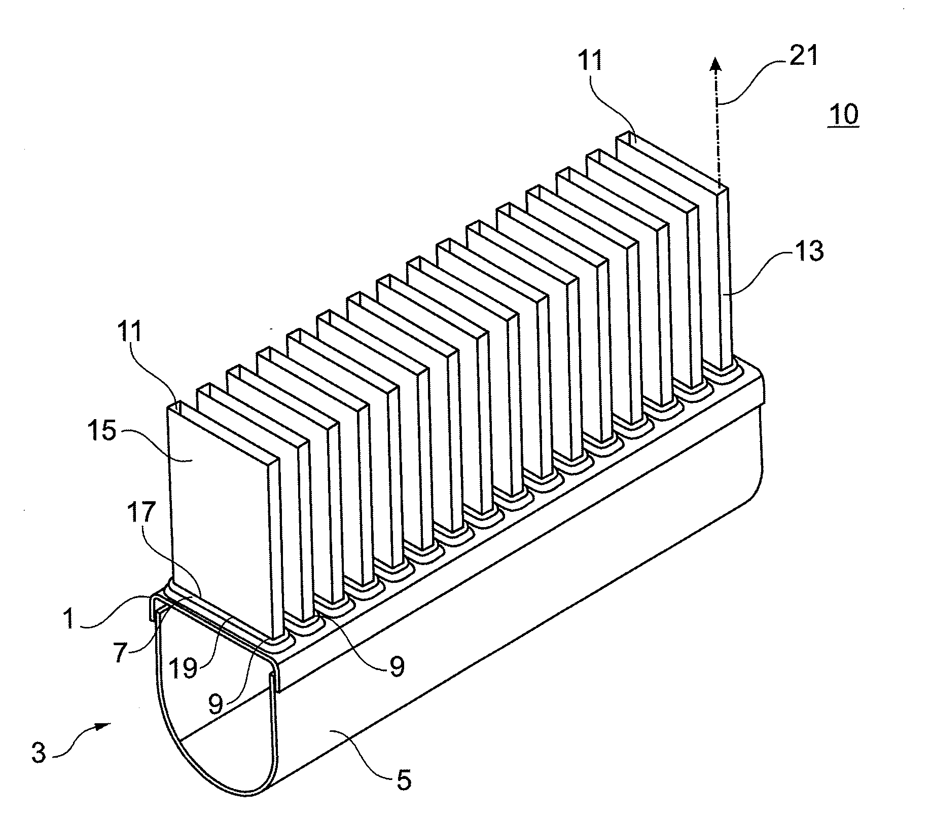
[0047]A heat exchanger according to the invention is realized according to an example embodiment in the form of a charge air cooler for direct charge air cooling and can be used for heat transfer between charge air and a coolant, such as air. In an alternative embodiment, the charge air cooler can be realized for indirect charge air cooling, whereby the coolant can be water. These and other heat exchangers can be used in particular for charge air cooling, or generally charge fluid cooling, in mobile applications, e.g., commercial vehicles. In the present case, the heat exchanger has a block comprising a radiator network for the separated heat-exchanging guiding of the charge air and the coolant. For this purpose, the block has a number of flow channels through which charge air can flow and which in addition have a heat-conducting member in the form of an inner fin attached to an inner channel surface and a heat-conducting member in the form of an outer fin attached to an outer chann...


PUM

PropertyMeasurementUnit
Angleaaaaaaaaaa
Distanceaaaaaaaaaa

Abstract

A heat exchanger is provided for heat transfer between a first fluid, particularly charge air or an exhaust gas, and a second fluid, particularly a coolant, which has: a block for the separated and heat-exchanging guiding of the first and second fluid, the block which has a number of flow channels through which the first fluid can flow, at least one box which is assigned to the block and is flow-connected to the flow channels, and at least one base, which is provided with one or with more through openings for feeding through the flow channels between the block and the box, whereby at least one through opening is formed as a passage with a collar. The invention provides that the collar has a near-bottom section and an end-side section, whereby a wall cross section of the end-side section is smaller than a wall cross section of the near-bottom section and between the near-bottom and end-side section at least one shoulder is disposed, which has a shoulder contour running transverse to the contour of the near-bottom section and / or the end-side section and whereby the end-side section is inclined away from a passage axis. A use and manufacturing process are also provided.

Description

[0001]This nonprovisional application claims priority under 35 U.S.C. §119(a) to German Patent Application No. 10 2008 036 975.6, which was filed in Germany on Aug. 8, 2008, and to German Patent Application No. 10 2008 051 896.4, which was filed in Germany on Oct. 16, 2008, and which are both herein incorporated by reference.BACKGROUND OF THE INVENTION[0002]1. Field of the Invention[0003]The present invention relates to a heat exchanger for heat transfer between a first fluid and a second fluid, that includes: a block for the separated and heat-exchanging guiding of the first and second fluid, the block having a plurality of flow channels through which the first fluid can flow; at least one box which is assigned to the block and which is flow-connected to the flow channels; and at least one base, which is provided with one or more through openings for feeding through the flow channels between the block and the box. Whereby at least one through opening is formed as a passage with a c...

Claims


Application Information

Patent Timeline
IPC IPC(8): F28F9/02F28F9/04B21D53/02
CPCY10T29/49373B21D41/02F28F9/182Y10T29/4935B21D53/02F28D1/05366
Inventor SAUMWEBER, CHRISTIANSCHILL, STEFAN
Owner BEHR GMBH & CO KG
Why Eureka
Try Eureka