Radio wave lens antenna device

a technology of antenna device and wave wave, which is applied in the direction of antenna details, antennas, basic electric elements, etc., can solve the problems of low signal reception sensitivity and easy affect of antenna device, and achieve the effect of subtly lowering the signal reception sensitivity and reducing the collection of rainwater

Inactive Publication Date: 2010-02-18
SKY PERFECT JSAT CORPORATION +1
View PDF2 Cites 196 Cited by
  • Summary
  • Abstract
  • Description
  • Claims
  • Application Information

AI Technical Summary

Benefits of technology

[0023]The radio wave lens antenna device according to the present invention includes a cover that covers part of the antenna device to function as an ice-snow, water resistant means that prevents rain, snow, and ice from collecting on the surface of the Luneburg lens or water from running frontward to the antenna element. This prevents rain water and melted snow from collecting on the surface of the lens. A radio wave lens antenna device that includes a barrier arranged on the surface of the cover does not function to prevent the collection of rain, snow, and ice. However, rainwa

Problems solved by technology

However, when rain falls or snow melts, the antenna device is easily affected by water that collects on or

Method used


Image

  • Radio wave lens antenna device
  • Radio wave lens antenna device
  • Radio wave lens antenna device

Examples


Embodiment Construction

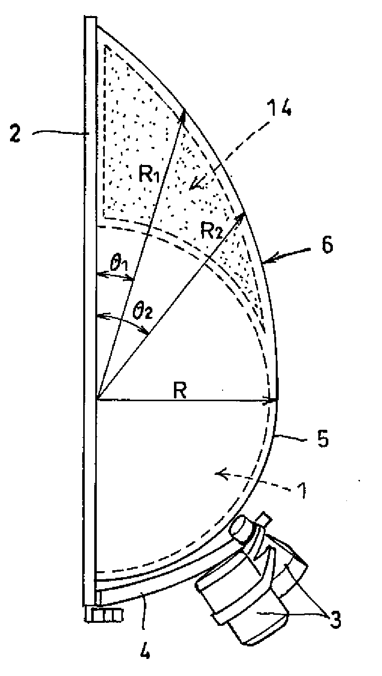
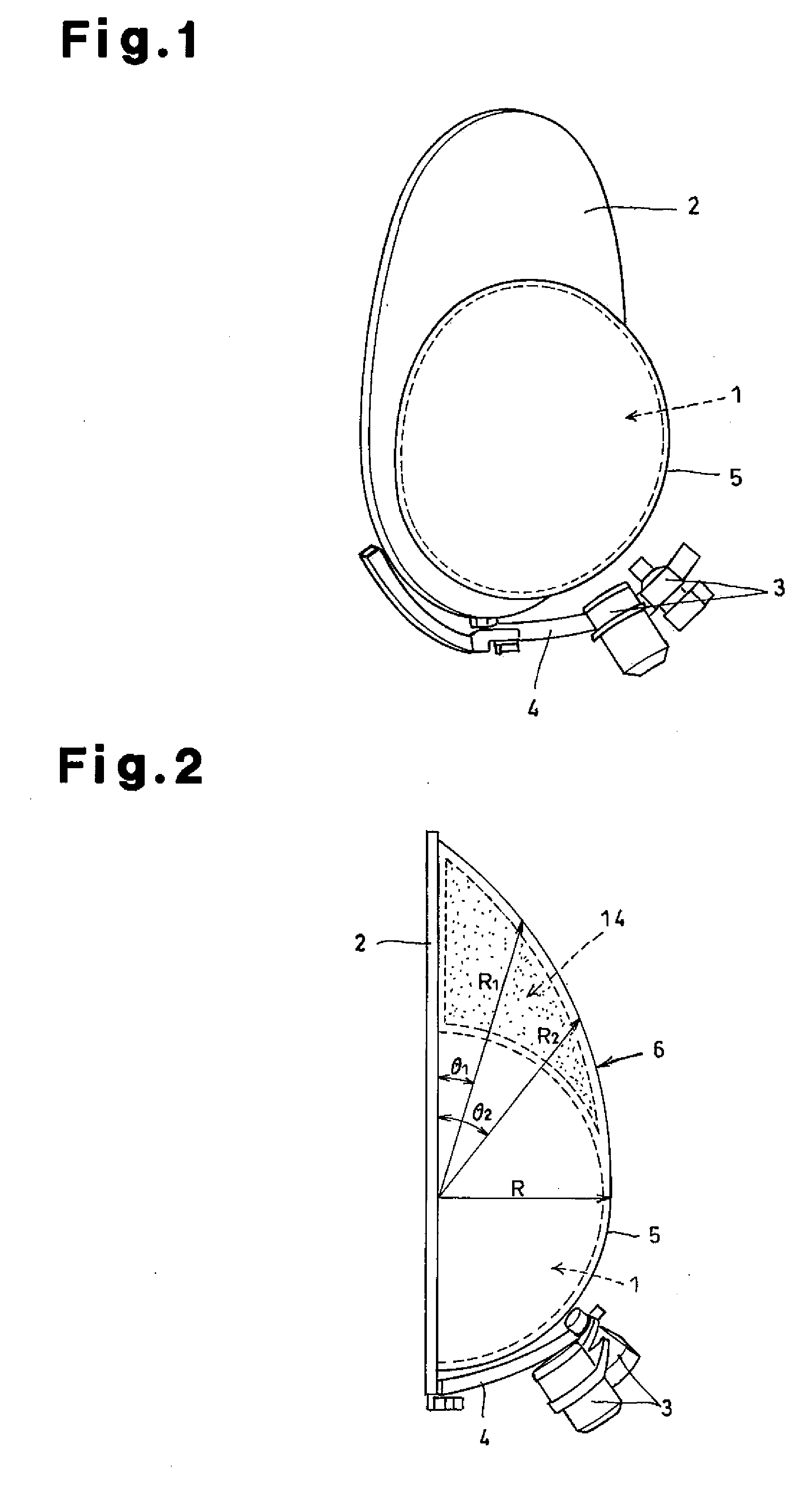
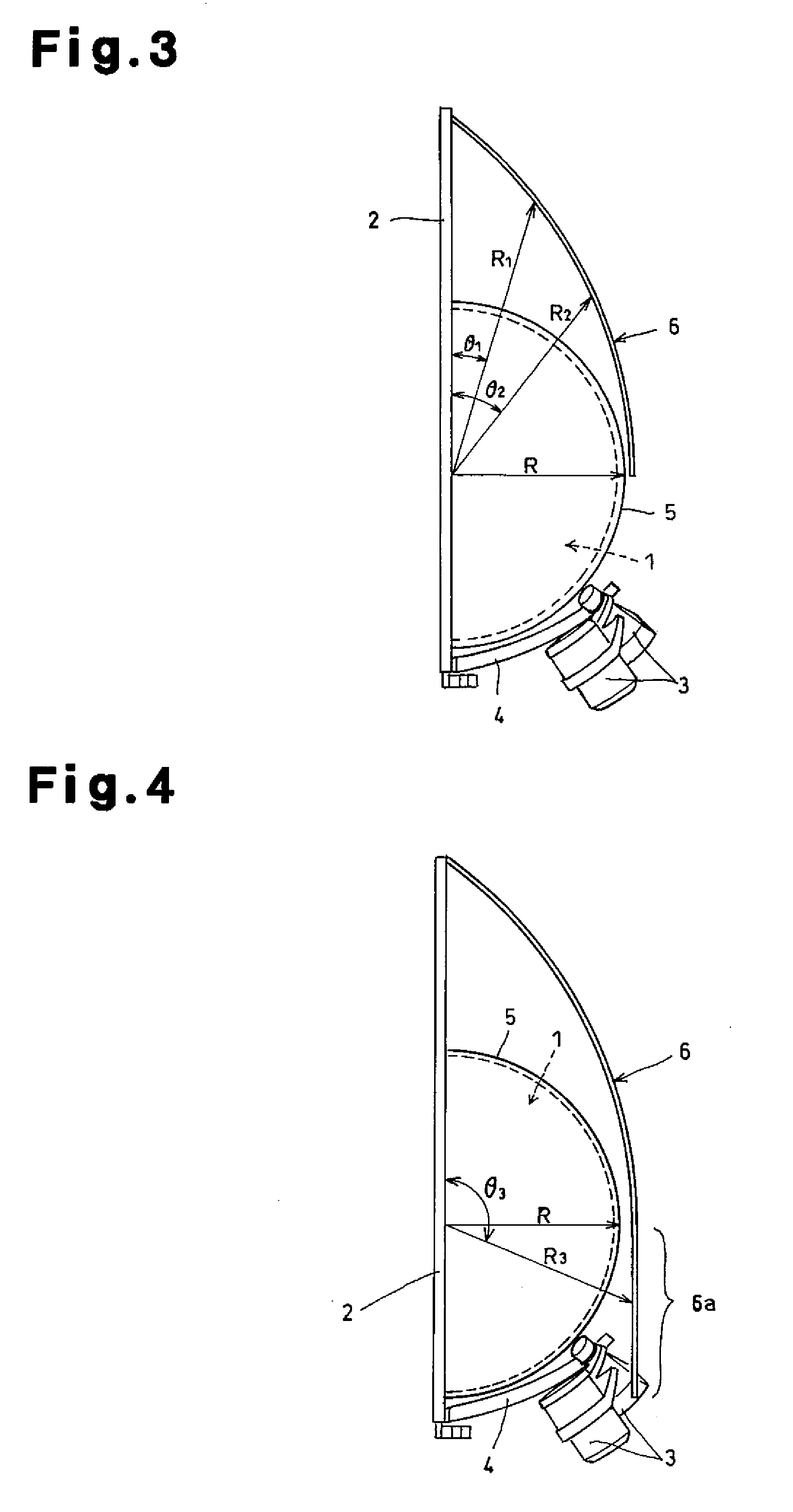
[0070]One embodiment of the present invention will now be discussed with reference to the accompanying drawings. A radio wave lens antenna device according to the present invention includes a semispherical Luneburg lens (hereinafter, simply referred to as the lens) 1, which is shown in FIG. 1, a radio wave reflection plate (hereinafter, simply referred to as the reflection plate) 2, antenna elements 3, and a holder 4. The reflection plate 2 lies along a bisectional surface of the sphere of the lens 1 and is larger than the diameter of the lens. The antenna elements 3 are arranged at a focal point of the lens. The holder 4 holds the lens elements 3.

[0071]The lens 1 is formed by a dielectric, has an internal dielectric constant that substantially varies between 2 to 1 from the center toward the outer side, and has a focal point located near the spherical surface. A semispherical first cover 5 is formed from resin, has a smooth surface, and covers the periphery of the lens 1 to protect...


PUM


Abstract

A radio wave lens antenna device including a semispherical Luneburg lens and a radio wave reflection plate. The radio wave lens antenna device prevents the signal reception sensitivity from being lowered in rain or snow. The radio wave lens antenna device includes a semispherical Luneburg lens 1, a radio wave reflection plate 2 that is larger than the diameter of the lens, an antenna element 3, and a holder 4 that holds the antenna element. The radio wave reflection plate 2 is arranged in an erected state. An ice-snow-water resistant means, which includes a first cover 5 and a second cover 6, prevents rain, snow, and ice from collecting and running off the Luneburg lens.

Description

RELATED APPLICATIONS[0001]This application is the U.S. National Phase under 35 U.S.C. §371 of International Application No. PCT / JP2006 / 311419, filed on Jun. 7, 2006, the disclosure of which Application is incorporated by reference herein.FIELD OF THE INVENTION[0002]The present invention relates to a radio wave lens antenna device that uses a Luneburg lens, and more particularly, to a radio wave lens antenna device that prevents the signal reception sensitivity from being lowered when rain falls or snow melts.BACKGROUND OF THE INVENTION[0003]It is anticipated that a radio wave lens antenna using a Luneburg lens can be employed as a multibeam-applicable antenna device enabling simultaneous communication with a plurality of communication peers. Further, such radio wave lens antennas have become able to take the place of parabolic antennas as geostationary satellite antenna devices.[0004]A Luneburg lens, which is formed by a dielectric, basically has a spherical shape. However, to minia...

Claims


Application Information

Patent Timeline
IPC IPC(8): H01Q19/06H01Q19/10H01Q1/02
CPCH01Q1/42H01Q1/421H01Q19/062H01Q15/08H01Q3/04
Inventor KURODA, MASATOSHIKIMURA, KOICHIKISHIMOTO, TETSUOYOKOTA, MASAOISHIBASHI, YOSHIYUKIKAMISE, YASUHIRO
Owner SKY PERFECT JSAT CORPORATION
Why Eureka
Try Eureka