

Liquid crystal display device
a liquid crystal display and display device technology, applied in non-linear optics, instruments, optics, etc., can solve the problems of lc panel edge region, lc panel b>50/b> becoming more susceptible to external impact or vibration, and the electronic device mounted therein is not implemented in a small size and light weight, so as to prevent damage to the lc panel
- Summary
- Abstract
- Description
- Claims
- Application Information
AI Technical Summary
Benefits of technology
Problems solved by technology
Method used
Image

Examples
first embodiment
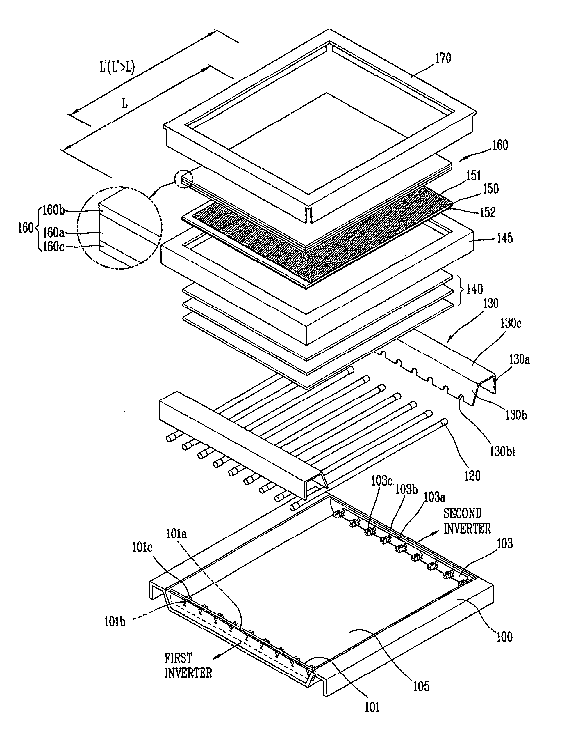
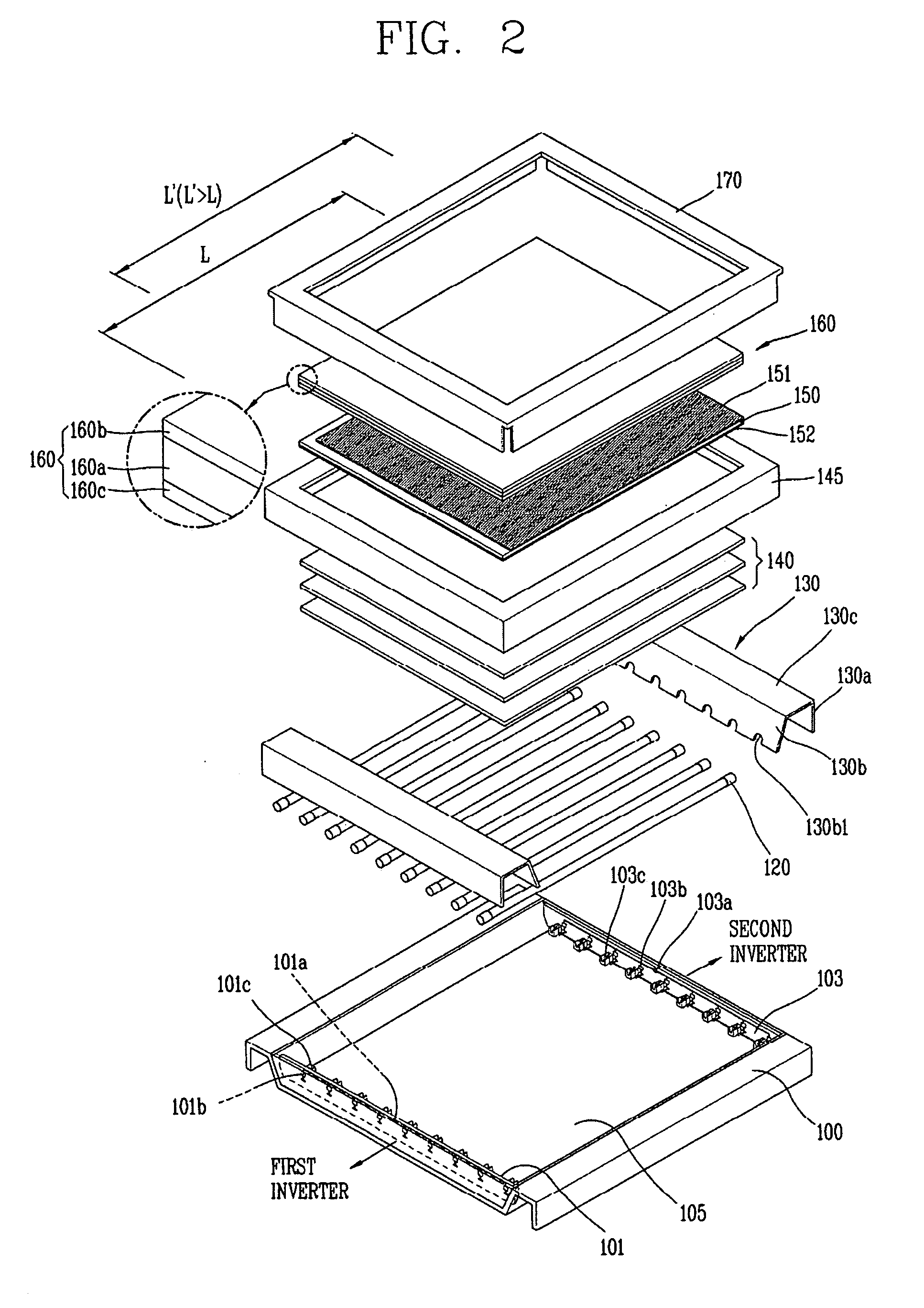
[0027]FIG. 2 is an exploded perspective view of an LCD device according to the present invention, and FIG. 3 is a sectional view showing a coupled state of the LCD device of FIG. 2.
[0028]As shown in FIGS. 2 and 3, the LCD device according to a first embodiment of the present invention comprises a backlight unit (not shown) for receiving a voltage from outside and providing light, an LC panel 150 disposed above the backlight unit for displaying an image, and a functional member 160 disposed on the LC panel 150 for preventing damage of the LC panel 150 due to an impact when the LC panel 150 moves.
[0029]Here, the functional member 160 may include a tempered substrate 160a serving as a protection member for protecting the LC panel 150 from an external impact, and an anti-reflect layer 160b disposed on the tempered substrate 160a for reducing reflectivity of light incident from outside. Moreover, the functional member 160 may further include an adhesion layer 160c formed of the same refr...
second embodiment
[0058]FIG. 4 is a sectional view of an LCD device according to the present invention.
[0059]Referring to FIG. 4, the LCD device according to a second embodiment of the present invention comprises an LC panel 250, a backlight unit disposed below the LC panel 250 for providing light, a functional member 260 disposed on the LC panel 250 within a size range of the LC panel 250, and an impact damping member 247 disposed to be spacing from one or more sides of the functional member 260 for absorbing an impact of the functional member 260 when the LC panel 250 moves. Here, the impact damping member 247 is provided on the main support 245.
[0060]In the LCD device according to the second embodiment of the present invention, the length (L′) of one or more sides of the functional member 260 disposed on the LC panel 250 is formed to be shorter than the length (L) of the LC panel 250. Here, the impact damping member 247 is disposed at the stepped inner portion (A) of an upper frame of the main sup...
third embodiment
[0067]Referring to FIG. 5, the LCD device according to the present invention comprises an LC panel 350, a backlight unit disposed below the LC panel 350 for providing light, a functional member 360 disposed on the LC panel 350 within a size range of the LC panel 350, an upper cover 370 coupled to an upper edge region of the functional member 360, and an impact damping member 347 disposed to be spacing from one or more sides of the functional member 360 for absorbing an impact of the functional member 360 when the LC panel 350 moves. Here, the impact damping member 347 is attached or coupled onto the upper cover 370.
[0068]In the same manner as the second embodiment, in the LCD device according to the third embodiment of the present invention, the length (L′) of one or more sides of the functional member 360 disposed on the LC panel 350 is formed to be shorter than the length (L) of the LC panel 350. Here, the impact damping member 347 is disposed at the stepped inner portion (A) of a...
PUM
 Abstract
Description
Claims
Application Information