
Electric Power Distribution System

Active Publication Date: 2010-02-18
AUTONETWORKS TECH LTD +2
View PDF12 Cites 1 Cited by
  • Summary
  • Abstract
  • Description
  • Claims
  • Application Information

AI Technical Summary

Benefits of technology

[0007]The present invention has been completed in view of the circumstances described above. It is an object of the present invention to increase the water drainage efficiency on the top face of the electrical connection box.
[0011]According to the present invention, water that has flowed into the top face of the electrical connection box by penetrating through the gap between the cover and the parts accommodation portions can be reliably drained, and thus there is no concern that the water will remain on the top face of the electrical connection box.

Problems solved by technology

In this structure, while the cover mounted on the electrical connection box covers the top face of the electrical connection box, because the parts accommodation portions are exposed on the outside face of the cover, there is a concern that water adhering to the top face of the cover may flow inside the top face of the electrical connection box through gaps between the opening portion of the cover and the parts accommodation portions.

Method used


Image

  • Electric Power Distribution System
  • Electric Power Distribution System
  • Electric Power Distribution System

Examples


example 2

Illustrative Example 2

[0108]Next, the second illustrative example, which embodies the present invention, will be explained with reference to FIG. 14. The electrical connection box P of the second illustrative example forms a communicating groove 60 on the top face of the main body portion 30 of the fuse block 23 of the electrical connection box P in the first illustrative example. Because the other components are identical to those of the first illustrative example, identical reference numerals are used to denote the identical components, and the explanations of the structures, the operations, and the effects are omitted.

[0109]The communication groove 60 is formed so as to enable the pair of left and right first drainage grooves 35 to communicate with each other, and the communication groove 60 is formed so as to extend from the end portion of the rear groove 35R of each of the first drainage grooves 35 such that the rear groove 35R is extended in a straight line towards the side op...

example 3

Illustrative Example 3

[0112]Next, a third illustrative example, which embodies the present invention, will be explained with reference to FIG. 15 and FIG. 16. The electrical connection box P of the third illustrative example is provided with, in the second illustrative example, a pair of front and rear communication grooves 63F and 63R, which are substantially parallel to each other, with an interval therebetween in the front-back direction orthogonal to the direction of separation (the left-right direction) between the pair of drainage grooves 35. The width dimension of these communication grooves 63F and 63R is larger than that of the front grooves 35F and the rear grooves 35R, and the front inside face of the front communication groove 63F is continuously flush with the front inside face of the front grooves 35F and the back inside face of the rear communication groove 63R is continuously flush with the back inside face of the rear grooves 35R. Specifically, the front inside face...


PUM


Abstract

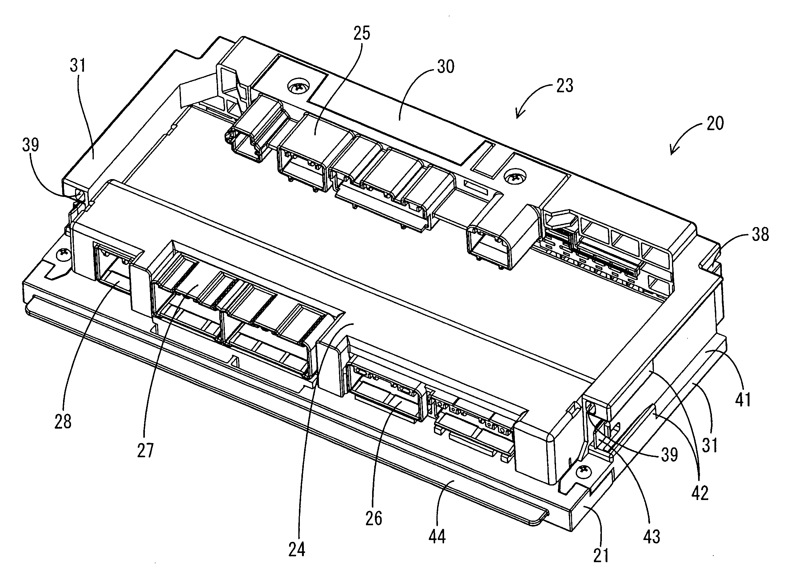
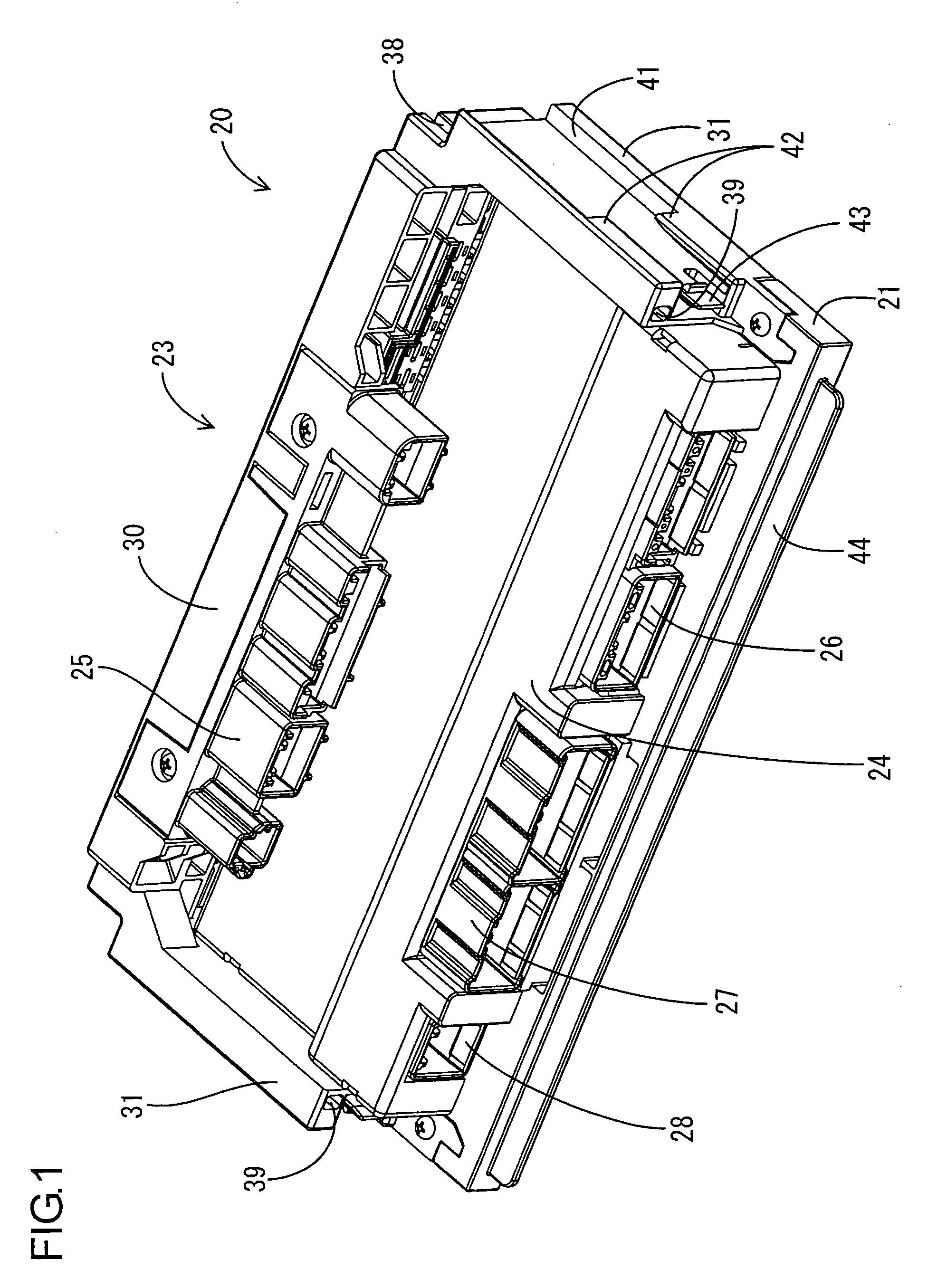
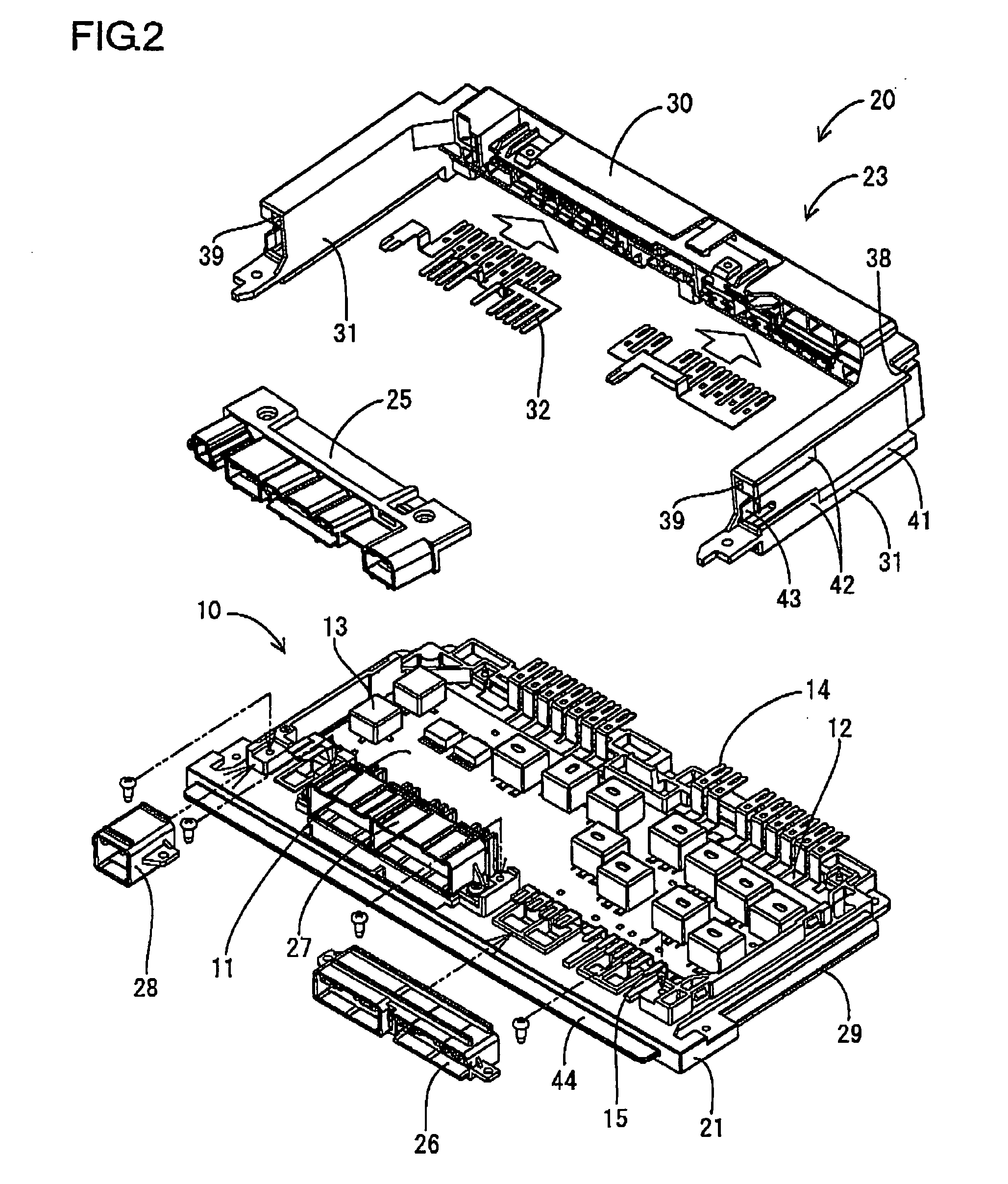
There is a concern that water on the top surface of a cover 50A will penetrate the top face of a case 20 through gaps between an opening portion 51H and parts accommodation portions 34 because the parts accommodation portions 34 are exposed to the outside at the opening portion 51H on the top face of the cover 50A while the electrical connection box P is positioned in the cover 50A. Because drainage grooves 35 and 36, which reach the drainage channels 38 on the outside face of the case 20, are formed on the top face of the case 20, water that remains on the top face of the case 20 (the main body portion 30) is reliably drained by flowing into the drainage grooves 35 and 36.

Description

[0001]This is a Division of application Ser. No. 11 / 578,936 filed Oct. 19, 2006. The disclosure of the prior application is hereby incorporated by reference herein in its entirety.TECHNICAL FIELD[0002]The present invention relates to an electric power distribution system.BACKGROUND ART[0003]An example of an electric power distribution system mounted in an automobile is one that houses an electrical connecting box in a housing shaped cover. The electrical connection box has a structure in which a circuit assembly is accommodated in a case, and the circuit assembly is structured to include a circuit board, bus bars that are wired along the reverse face of the circuit board, and switching members such as relays and the like that are mounted on the obverse side of the circuit board. The case is structured to include a frame shaped member that is disposed and secured along the outside perimeter of the circuit board, a cover that is mounted so as to cover the circuit board from the obvers...

Claims


Application Information

Patent Timeline
Patent Type & Authority Applications(United States)
IPC IPC(8): H02B1/04H02B1/18H01J5/00
CPCH01R13/518H05K7/026H05K5/066H01R13/5227H01R12/716H01R12/721H01R12/724
Inventor SASAKI, YOSHIKAZUKITA, YUKINORI
Owner AUTONETWORKS TECH LTD
Learn More