
Modular high-power fuse carrier

Inactive Publication Date: 2010-02-18
ROCKWELL AUTOMATION TECH
View PDF3 Cites 9 Cited by
  • Summary
  • Abstract
  • Description
  • Claims
  • Application Information

AI Technical Summary

Benefits of technology

[0005]The present invention provides a fuse carrier that converts a variety of different fuse types and sizes into a standard element that may be readily integrated in pre-wired or pre-manufactured assemblies. Generally, the invention provides for a rectangular housing that is readily integrated into an equipment drawer and which includes a range of mounting points that allows a variety of different fuse types and capacities to be held within the housing in a standard volume. By wiring the housing into place, the end user may, with relatively little effort and with no rewiring, freely select among a variety of different fuses and even change among different types and capacities after installation.
[0010]It is thus an object of at least one embodiment of the invention to provide a structure allowing maximum flexibility in fuse attachment and the ability to pre-populate multiple mounting points at low cost overhead.
[0016]It is thus an object of at least one embodiment of the invention to maximize airflow and fuse accessibility when ganged fuses are not required.
[0018]Thus it is an object of at least one embodiment of the invention to provide for a modular housing while retaining good airflow qualities that would be expected in non-modular construction where the fuses are mounted to a simple base plate or a custom fuse block.
[0026]It is thus an object of at least one embodiment of the invention to provide a simple method of providing multiple terminations within an insulating plastic housing.
[0028]It is thus another object of at least one embodiment of the invention to provide substantial flexibility in connector style.

Problems solved by technology

These fuse types have different form factors, including different lengths, diameters, and mounting styles depending on both the type and power capacity required, meaning that fuse types and capacities are generally not interchangeable within an installation.
Unfortunately, in order to allow the customer freedom in the choice of fuse type, a variety of different standard assemblies must be pre-manufactured or the installation of the fuses left to the field assembly by the customer.
These choices defeat the purpose of pre-manufacture.

Method used


Image

  • Modular high-power fuse carrier
  • Modular high-power fuse carrier
  • Modular high-power fuse carrier

Examples


Embodiment Construction

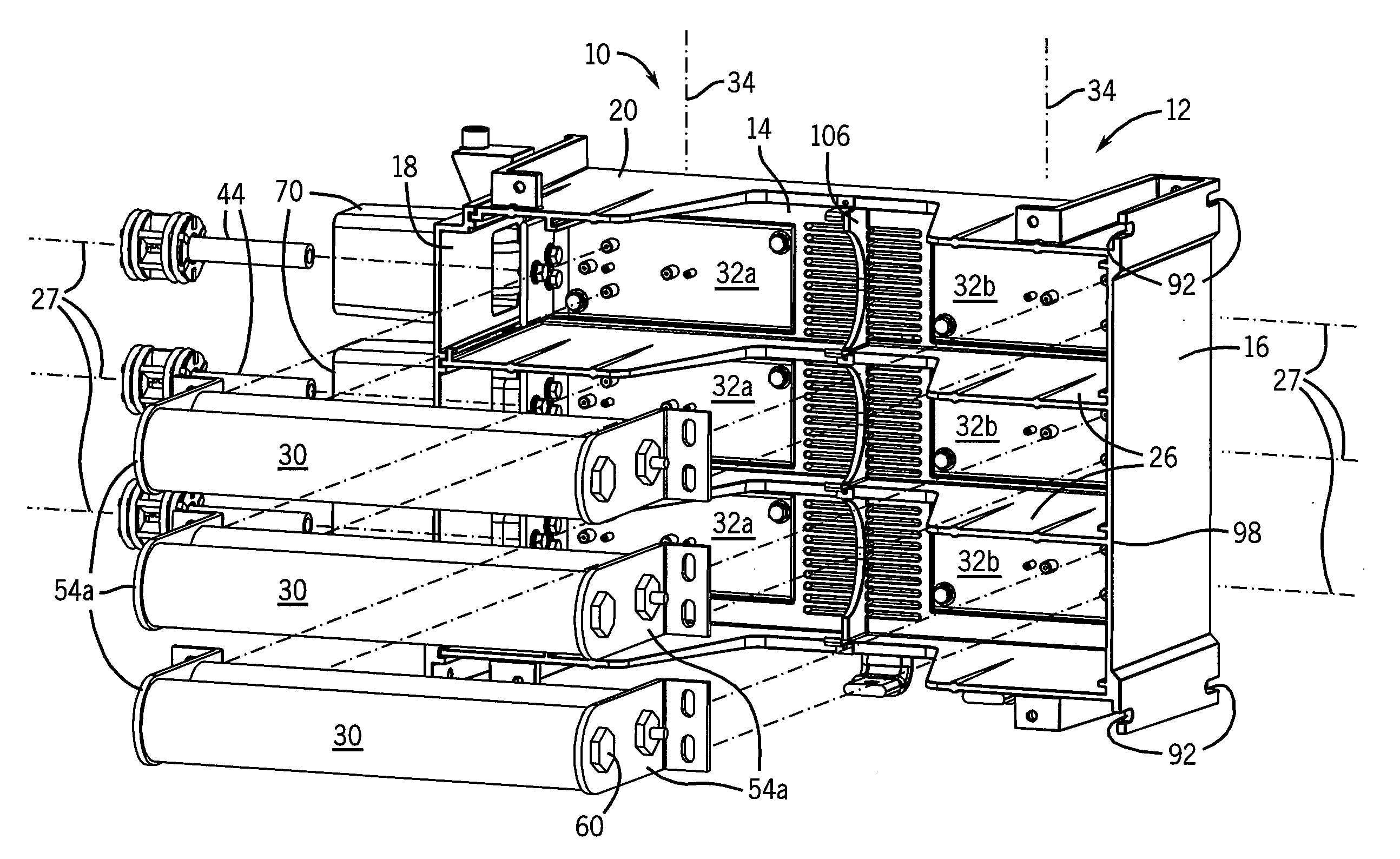
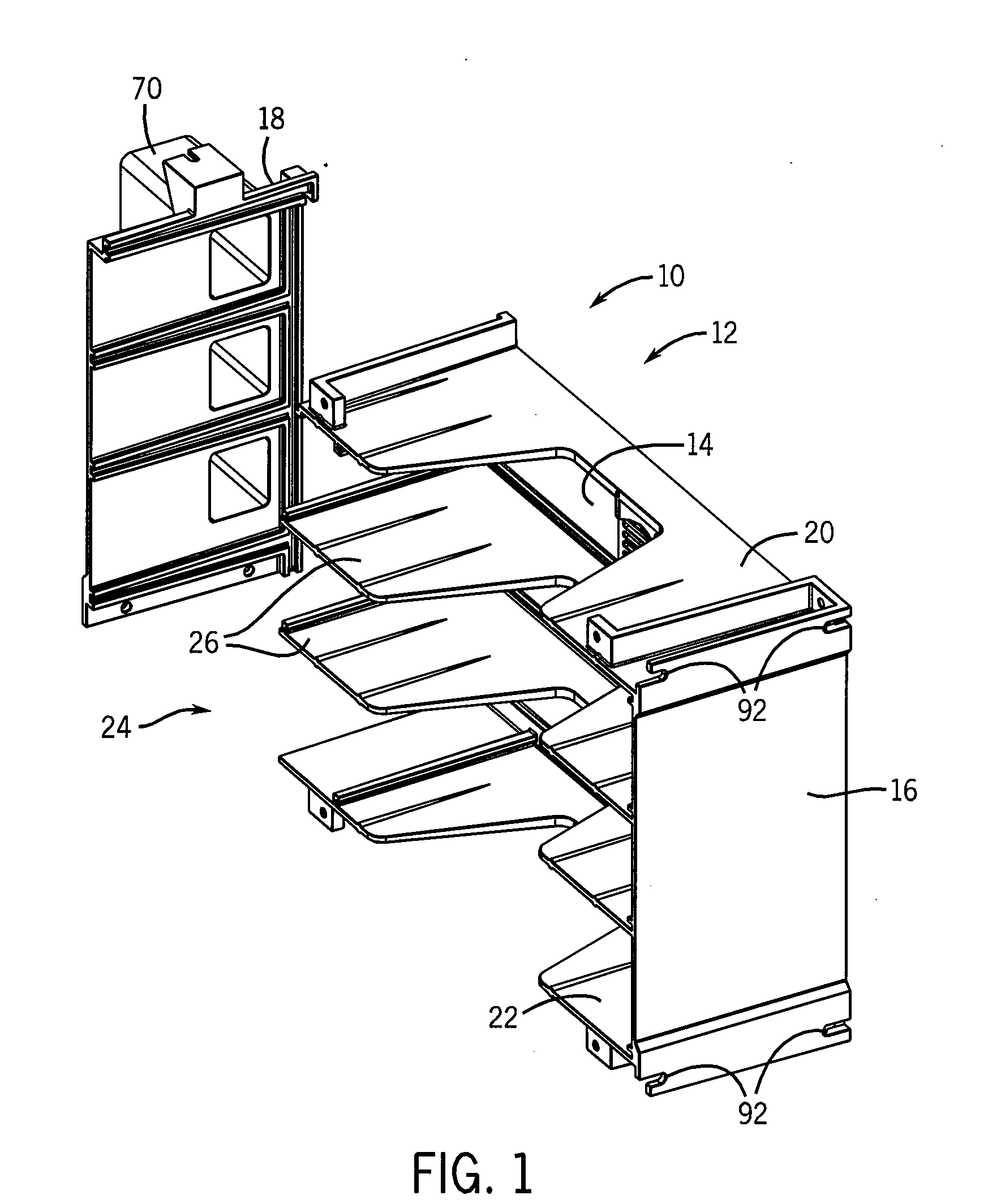
[0036]Referring now to FIG. 1, a modular fuse carrier 10 of the present invention provides for an electrically insulating, generally rectangular housing 12 having a substantially planar and rectangular base 14 surrounded by four upstanding and opposed walls including end walls 16 and 18 and sidewalls 20 and 22. The walls 16, 18, 20 and 22 form a generally rectangular frame defining an interior volume of the modular fuse carrier 10 open from a front face 24.

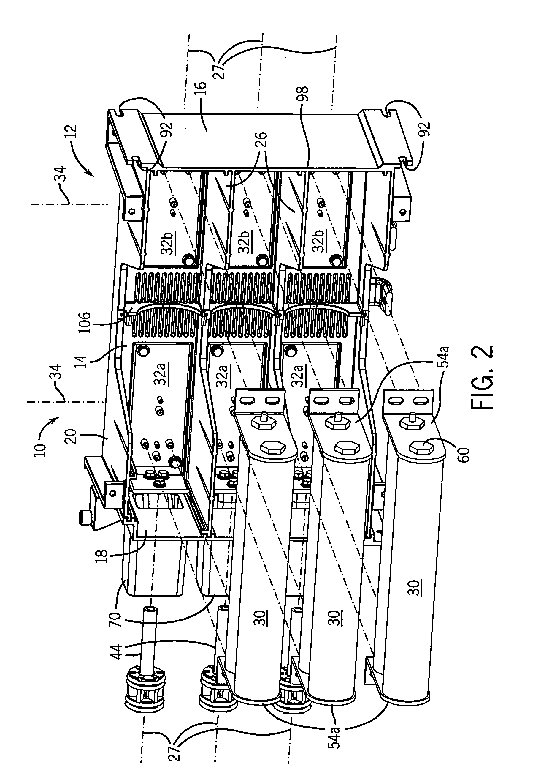
[0037]Referring also to FIG. 2, a set of two divider walls 26 extending from the base 14 generally parallel to the sidewalls 20 and 22 divide the interior volume into three rows along row axes 27 extending between the end walls 16 and 18. Each of these rows may accept one or more fuses 30. Although ANSI-type fuses 30 are shown, as will be described in more detail below, the present invention may accommodate any of the standard fuse configurations of DIN-type, ANSI-type fuse, and British Standard type mounts having ratings in the r...


PUM


Abstract

A modular fuse carrier provides an insulating housing of standard form factor incorporating adapter bus bars having multiple mounting points for different fuse brackets at different separations. The adapter bus bars may be attached to connectors and / or bus bars in fixed configurations to allow standardization and pre-manufacture of electrical assemblies that remain amenable to a wide variety of different fuse types and capacities.

Description

STATEMENT REGARDING FEDERALLY SPONSORED RESEARCHCROSS-REFERENCE TO RELATED APPLICATIONSBACKGROUND OF THE INVENTION[0001]The present invention relates to high-power electrical systems and, in particular, to an adapter for high-power electrical fuses used in such systems.[0002]High-power electrical fuses handling hundred of amperes at kilovoltages come in a variety of sizes and configurations including ANSI, DIN and British Standard types. These fuse types have different form factors, including different lengths, diameters, and mounting styles depending on both the type and power capacity required, meaning that fuse types and capacities are generally not interchangeable within an installation. While the different fuse types provide overlapping ranges of electrical functions, a customer will typically require a particular fuse type for reasons of standardization within a facility, availability, or electrical capacity requirements.[0003]Fuses are typically used in conjunction with other...

Claims


Application Information

Patent Timeline
IPC IPC(8): H01H85/20
CPCH01H85/20H01H85/203H01H85/205H02B11/26H01H2085/2065H01H2085/207H01H2085/2055
Inventor MASON, ANTHONY S.
Owner ROCKWELL AUTOMATION TECH
Learn More