Floodlight with tiltable beam

a technology of tilting beams and floodlights, applied in the field of floodlights, can solve the problems of complex operation and complicated mechanical means for moving and correct orienting of light beams, and achieve the effect of providing various light beam orientations easily and quickly

Inactive Publication Date: 2010-02-18
KONINKLIJKE PHILIPS ELECTRONICS NV
View PDF11 Cites 17 Cited by
  • Summary
  • Abstract
  • Description
  • Claims
  • Application Information

AI Technical Summary

Benefits of technology

[0006]It is an object of embodiments of the invention to provide a floodlight which can provide various light beam orientations easily and without the need of a complex mechanical positioning system.

Problems solved by technology

This translation movement requires complicated mechanical means for positioning properly one array with respect to the other and permitting one array to move with respect to the other.
Furthermore, correctly orienting the light beam is a complex operation because of the complexity of the mechanical means for positioning the arrays.

Method used


Image

  • Floodlight with tiltable beam
  • Floodlight with tiltable beam
  • Floodlight with tiltable beam

Examples


Embodiment Construction

[0020]In the instant specification, the beam width is measured according to the full-width half-maximum method (FWHM), which is well known in the art.

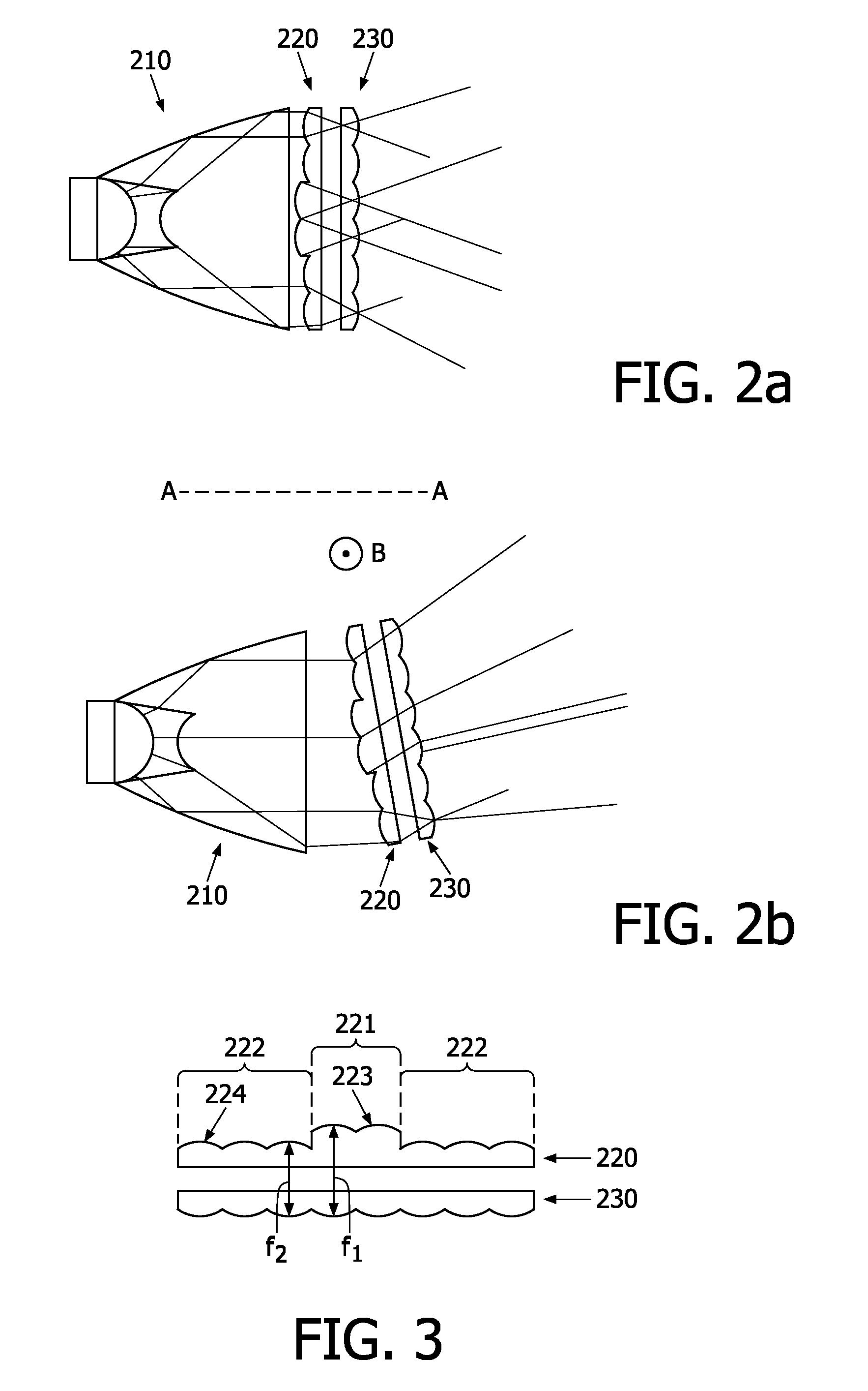
[0021]Lenses arrays consist of a plurality of lenses the optic axis of which are parallel two by two. A focal plane of a lenses array is a plane which is perpendicular to the optic axis of the lenses of said array and passes through the focal point of at least one lens of the lenses array. When two lenses arrays are described as parallel, it means that a focal plane of a first lenses array is parallel to a focal plane of a second lenses array.

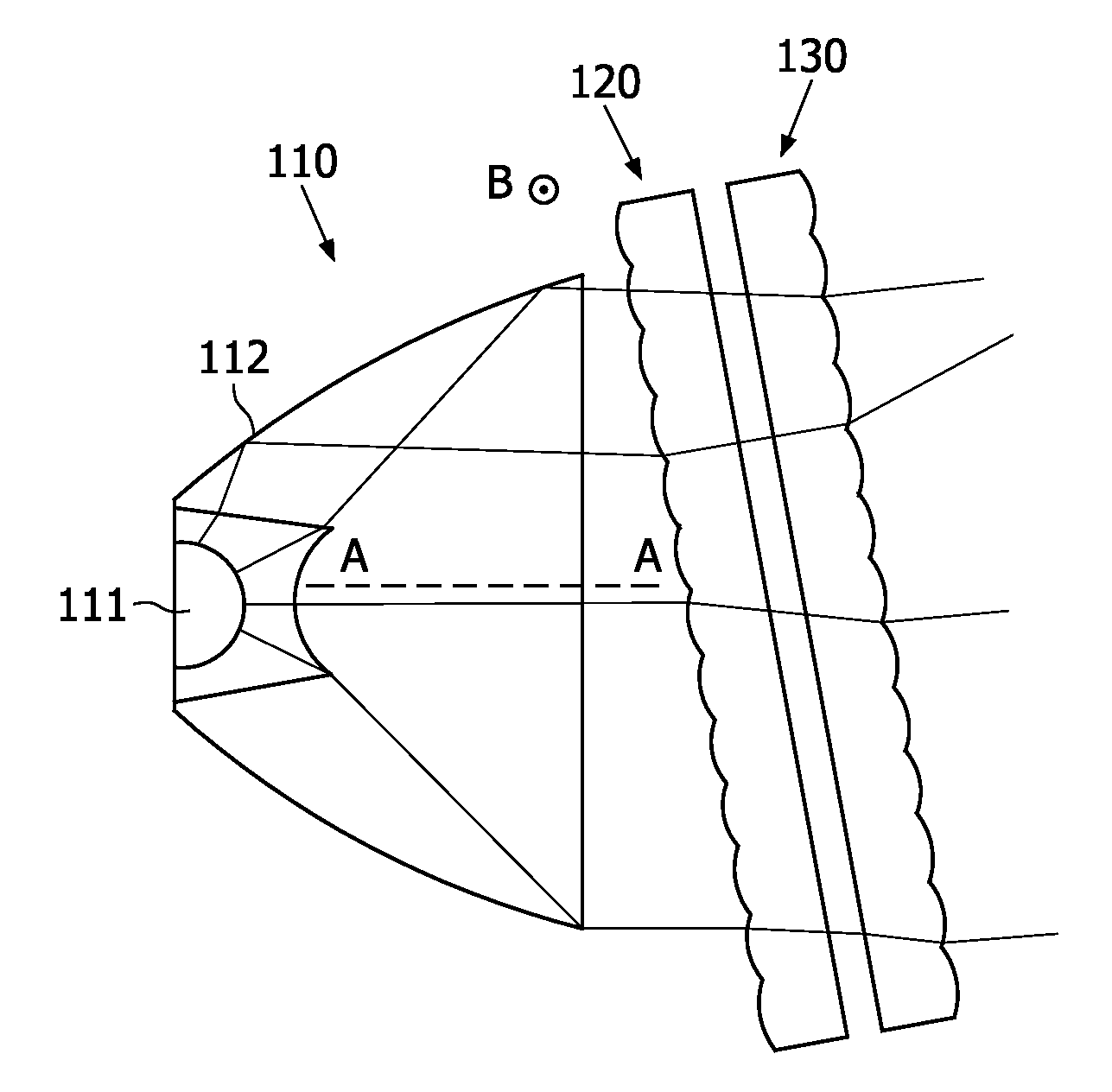
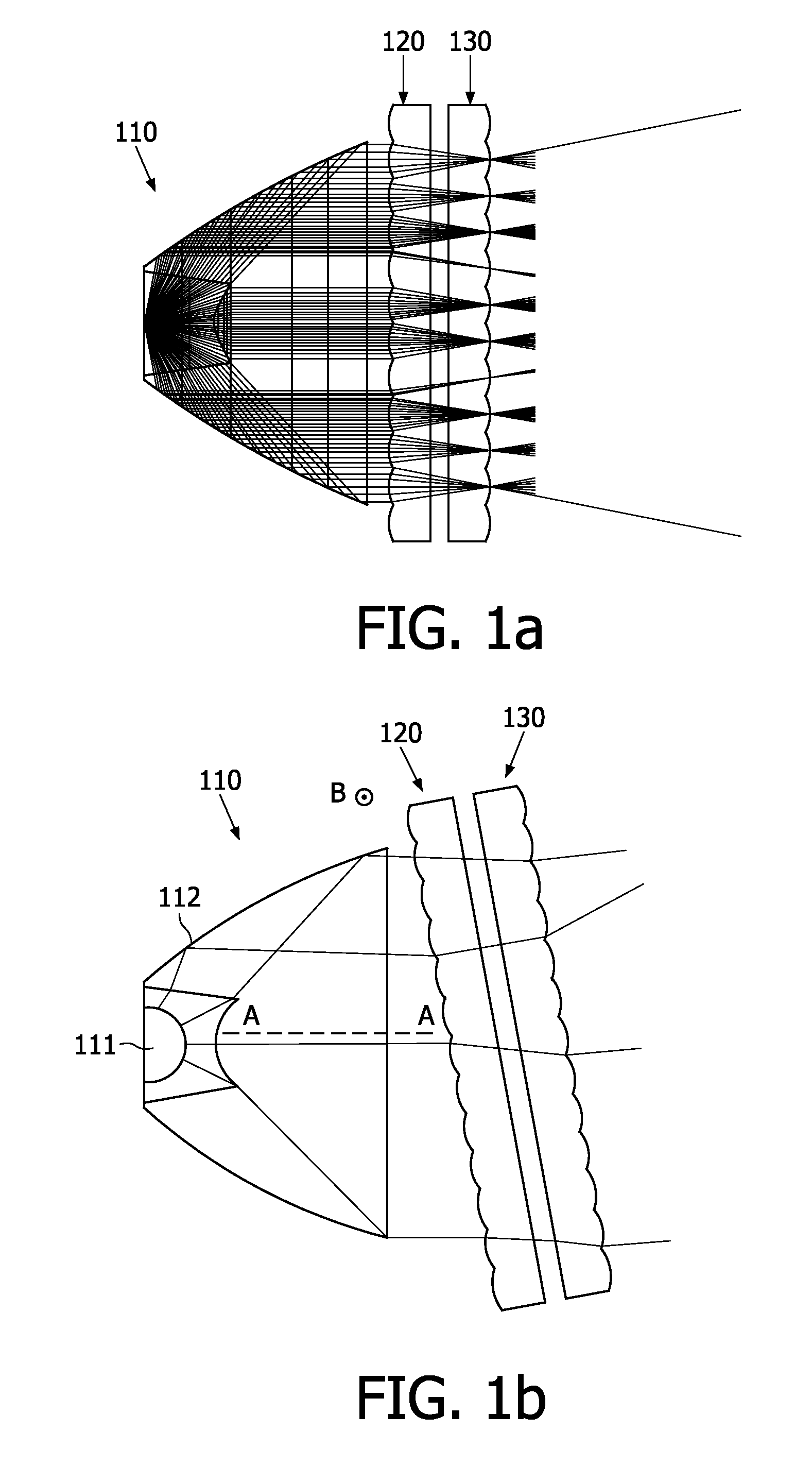
[0022]A floodlight in accordance with a first embodiment of the invention is depicted in FIGS. 1a and 1b. This floodlight comprises means 110 for generating a parallel beam. The parallel beam has a general direction AA. A first lenses array 120 is located on the path of the parallel beam. First lenses array 120 comprises a plurality of convergent lenses, for generating a plurality of convergent be...


PUM


Abstract

A floodlight comprises means (110) for generating a parallel beam having a general direction (AA), a first convergent lenses array (120) for generating a plurality of convergent beams from said parallel beam, and a second lenses array (130) parallel to and integral with said first lenses array. The floodlight further comprises means for rotating simultaneously said first and second lenses arrays about an axis perpendicular to the general direction of the parallel beam.

Description

FIELD OF THE INVENTION[0001]The invention relates to a floodlight intended to be used in various illumination applications. This invention is particularly relevant for stage, faæade or accent lighting.BACKGROUND OF THE INVENTION[0002]In the lighting field, various kinds of light beams are often required. On the one hand, when a faæade is to be illuminated, a wide light beam may be desired, so as to illuminate the whole faæade. On the other hand, a narrow light beam may be needed to illuminate only a detail of a faæade. To this end, various floodlights are used.[0003]Moreover, floodlights are often inserted into recessed cavities, for instance in a pavement, in a sidewalk or in a wall. Therefore, it is necessary that the light beam be properly oriented towards the element to be illuminated.[0004]International patent publication WO 2005 / 093319 discloses a floodlight wherein a light beam provided by a light-emitting diode (LED) may be tilted. This floodlight comprises a first array of ...

Claims


Application Information

Patent Timeline
Patent Type & Authority Applications(United States)
IPC IPC(8): F21S8/00F21V5/00
CPCF21V14/06F21W2131/10G02B3/0043G02B26/0875G02B3/0056G02B3/0062G02B3/0068G02B3/005
Inventor FOURNIER, DENISJOUFFRIEAU, MATTHIAS
Owner KONINKLIJKE PHILIPS ELECTRONICS NV
Why Eureka
Try Eureka