

Load Sign Recognition Apparatus and Load Sign Recognition Method
a technology of load sign recognition and load sign, which is applied in the direction of signalling/lighting devices, instruments, transportation and packaging, etc., can solve the problems of insufficient resistance of the technique, difficulty in recognizing the position, and misrecognization of luminance difference caused by shadow in the captured imag
- Summary
- Abstract
- Description
- Claims
- Application Information
AI Technical Summary
Benefits of technology
Problems solved by technology
Method used
Image

Examples
first embodiment
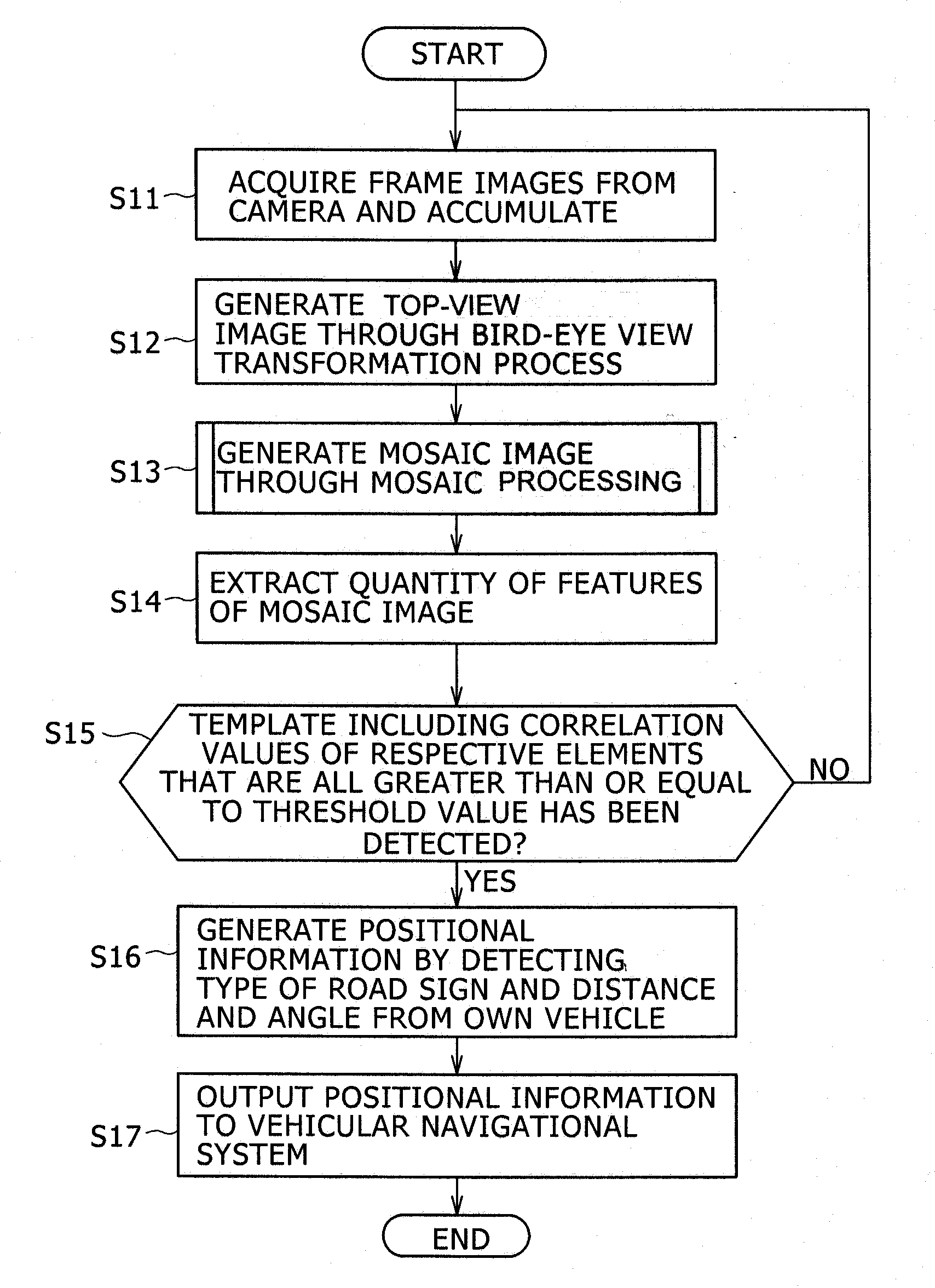
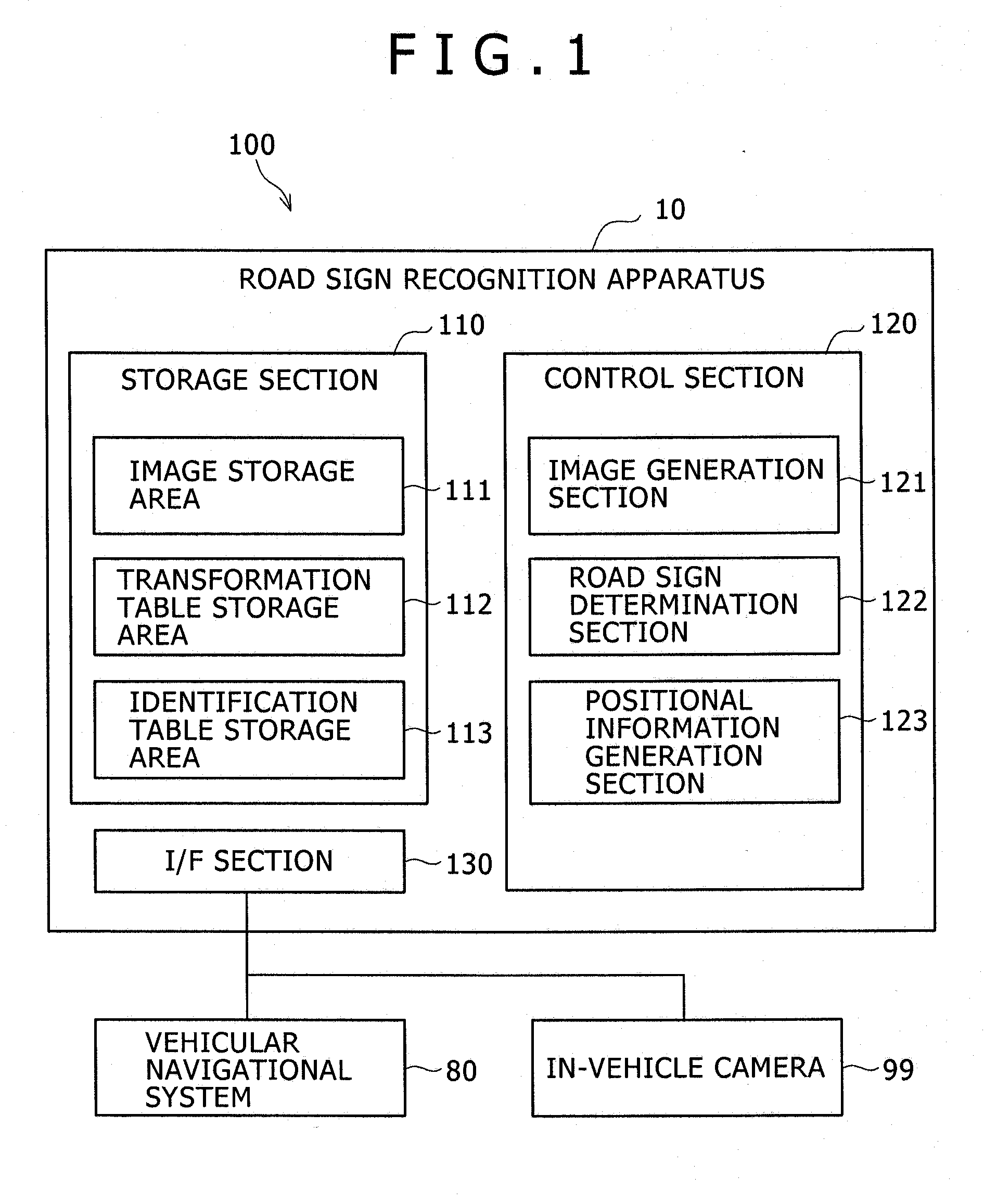
[0021]FIG. 1 is a block diagram illustrating a functional configuration of a road sign recognition system 100 of a first embodiment.
[0022]The road sign recognition system 100 includes a road sign recognition apparatus 10, a vehicular navigational system 80, and an in-vehicle camera 99.
[0023]The road sign recognition apparatus 10 includes a storage section 110, the control section 120, an interface section 130 (“I / F section,” below).
[0024]The storage section 110 includes an image storage area 111, a transformation table storage area 112, and an identification table storage area 113.
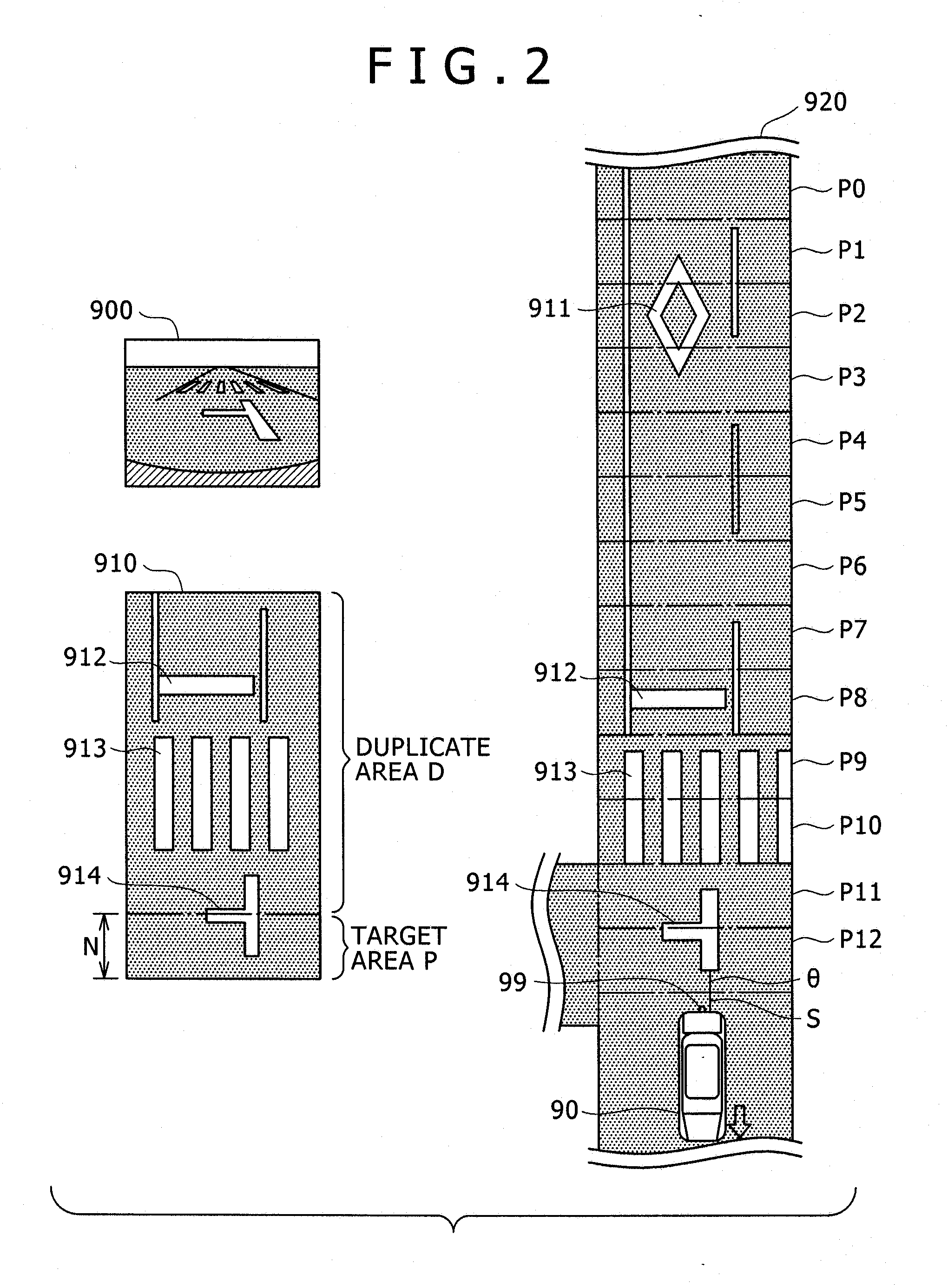
[0025]The image storage area 111 stores therein frame images acquired from the camera (in-vehicle camera 99), top-view image and mosaic images generated by an image generation section 121 from the frame images. FIG. 2 is a schematic view including examples of a frame image 900, a top-view image 910, and a mosaic image 920.
[0026]The transformation table storage area 112 stores therein a transformation table...
modified example 1
[0069]In the embodiment described above, template matching is execution for the mosaic image 920, for example, but it is not limited thereto. The method may be such that a predetermined processing area R is extracted from the mosaic image 920, and template matching is executed for the processing area R. A modified example 1, such as described above, is described in more detail below. FIG. 8(a) is a schematic view of a processing area R (P1-P8) and a transverse luminance component 22b corresponding thereto.
[0070]When, at step S14, having received from the image generation section 121 an instruction for extraction of a quantity of features, the road sign determination section 122 may extract an area inclusive of two road signs closest to the vehicle 90 from the mosaic image 920 as the processing area R. The number of road signs included in the processing area R is not limited to the above, and may be any number inasmuch as it is multiple.
[0071]For example, with reference to FIG. 8, th...
modified example 2
[0076]In the embodiment and modified example described above, the distance between road signs contained in the mosaic image 920 (and the processing area R thereof) does not necessarily conform with the distance between road signs of the quantity of features indicated in the template 13. In this case, there is a probability that, whereas the road signs are in the same combination, a record is not detected and hence the matching accuracy is reduced.
[0077]Of course, in the case where a template containing a variety of inter-road sign distances is provided, template matching with high accuracy can be accomplished. In this case, however, a very large number of templates is necessary.
[0078]Then, in the event that no conformance record is detected as a result of template matching at step S15, the road sign determination section 122 may execute a process in the manner that the template 13 is corrected to thereby improve the accuracy of the template 13. This is described in more detail below...
PUM
 Abstract
Description
Claims
Application Information