Coaxial Connector

Active Publication Date: 2010-02-18
CHEN TEN MAY
View PDF9 Cites 13 Cited by
  • Summary
  • Abstract
  • Description
  • Claims
  • Application Information

AI Technical Summary

Benefits of technology

[0007]The main object of the present invention is to provide a coaxial connector, wherein the housing is a one-piece design to simplif

Problems solved by technology

Therefore, the entire assembly process of the coaxial connector needs a plurality of assemblies, such as to cost much time and work and in the mean time reduce the efficiency of the process.
Further, for most coaxial connectors nowadays, their terminals and cables are fixed by means of soldering which may results in an unstable connection between the contact ends of the terminals, as such a more complicated process needed.
It needs to take much care while soldering because it may cause short-circuit resulting from the over-heated solder and/or too much solder slag.
The solderin

Method used


Image

  • Coaxial Connector
  • Coaxial Connector
  • Coaxial Connector

Examples


Example

[0028]The above-described objects, features and advantages of the present invention will be apparent in the following detailed descriptions of the preferred embodiments with reference to the accompanying drawings.

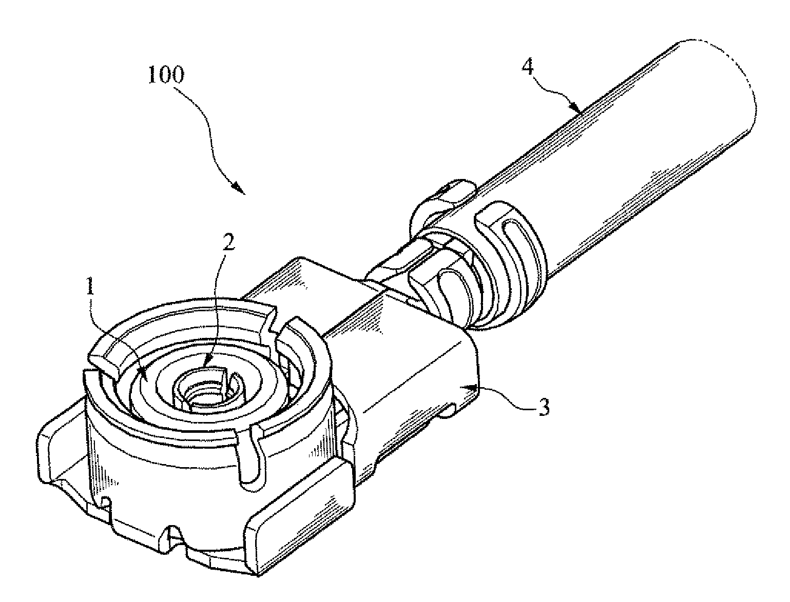
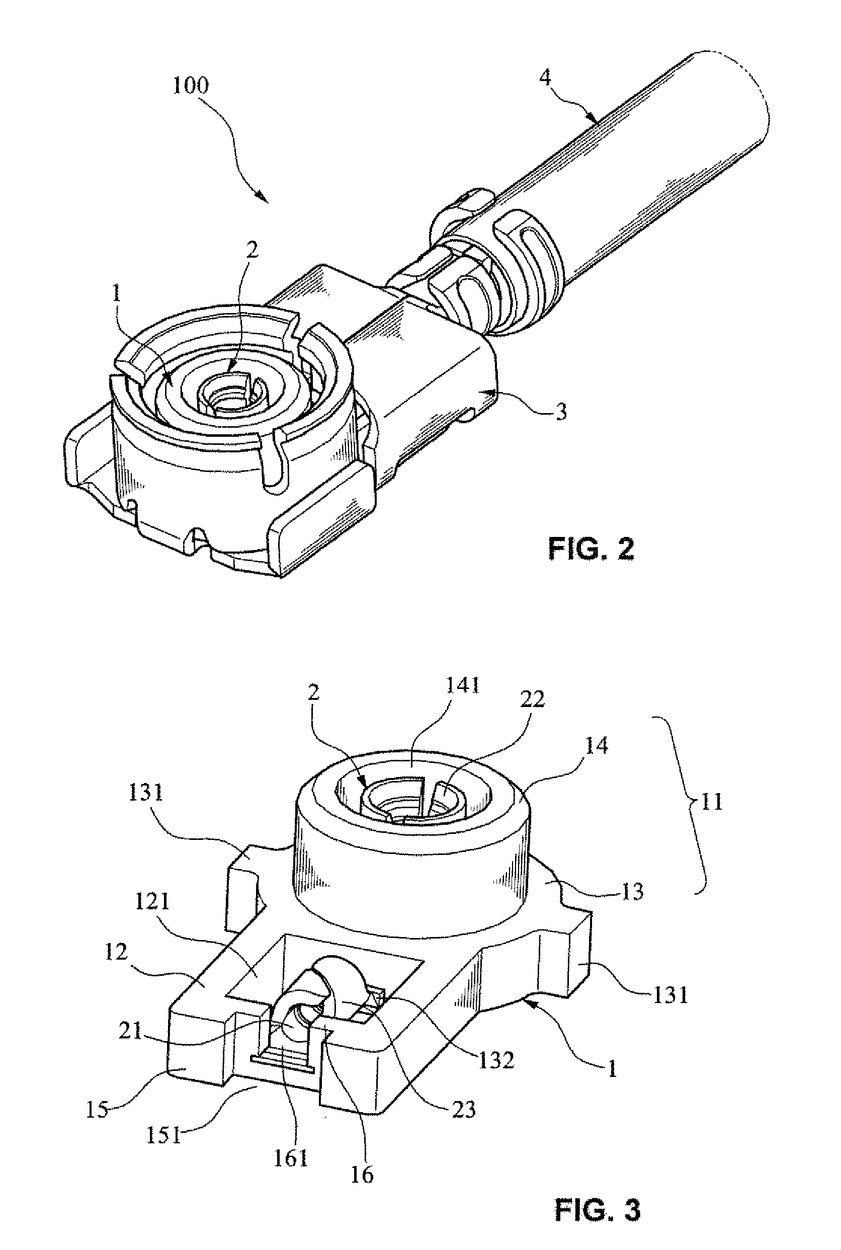
[0029]Refer to FIG. 2, which shows a preferred embodiment of coaxial connector 100 of the present invention. The coaxial connector 100 comprises an insulating body 1, a central terminal 2 disposed within the insulating body 1, a housing 3 surrounding the insulating body 1, and a coaxial cable 4 connected therewith.

[0030]Please refer to FIG. 3. The central terminal 2 and the insulating body 1 are formed to be an integrated assembly by insert molding. The insulating body 1 comprises a cylindrical portion 11 and a plate portion 12, and the cylindrical portion 11 includes a base 13 and a cylinder 14 protruding from the base. The cylinder 14 may have a hollow portion 141 for accommodating the contact 22 of the central terminal 2. The base 13 and the plate portion 12 are connecte...


PUM


Abstract

A coaxial connector includes an insulating body, a central terminal having a main rod comprising front and rear portions, and a housing. The front portion extends outwardly to form left and right wing-members. Wing-members can be bent to surround the front portion and to form a cylindrical contact. Each wing-member extends outwardly to form a sheet body. Tongue members are bendable to form fixing portions for fixing the insulating body by insert molding. The rear portion has fixtures for clamping the coaxial cable. The housing includes a plate member, a main portion for connecting one end of the plate member, and a cable-clamping member for connecting the other end of the plate member. The main portion has two supporting arms for clamping and holding the insulating body. Each supporting arm has a bottom fixture sheet. Side arms and the fixture members are bendable to fix.

Description

BACKGROUND OF THE INVENTION[0001]1. Field of the Invention[0002]The present invention relates to a coaxial connector, especially to a coaxial connector in which elements are first mold-formed and then assembled to be a finished article for transmitting high-frequency signals.[0003]2. Description of the Prior Art[0004]A coaxial connector is primarily used to connect a cable with an electronic apparatus to transmit high-frequency signals between them. In order to obtain highly distinct high-frequency signals, the requirements for the structure parts of the coaxial connectors are therefore more critical than usual connectors.[0005]A technology relating to the coaxial connectors can be found in Chinese patent application No. CN 01264762.4, which discloses a coaxial connector consisting of four elements, including an insulating body, a terminal disposed within the insulating body, a housing and a clamping means for fixing and supporting the coaxial connector; wherein the insulating body ...

Claims


Application Information

Patent Timeline
IPC IPC(8): H01R9/05
CPCH01R9/0518H01R24/40H01R2103/00H01R43/24H01R43/16
Inventor CHEN, TEN MAY
Owner CHEN TEN MAY
Why Eureka
Try Eureka