Safety syringe

Active Publication Date: 2010-02-18
PROTECTUS MEDICAL DEVICES
View PDF8 Cites 31 Cited by
  • Summary
  • Abstract
  • Description
  • Claims
  • Application Information

AI Technical Summary

Problems solved by technology

However, this results in an incre

Method used


Image

  • Safety syringe
  • Safety syringe
  • Safety syringe

Examples


Example

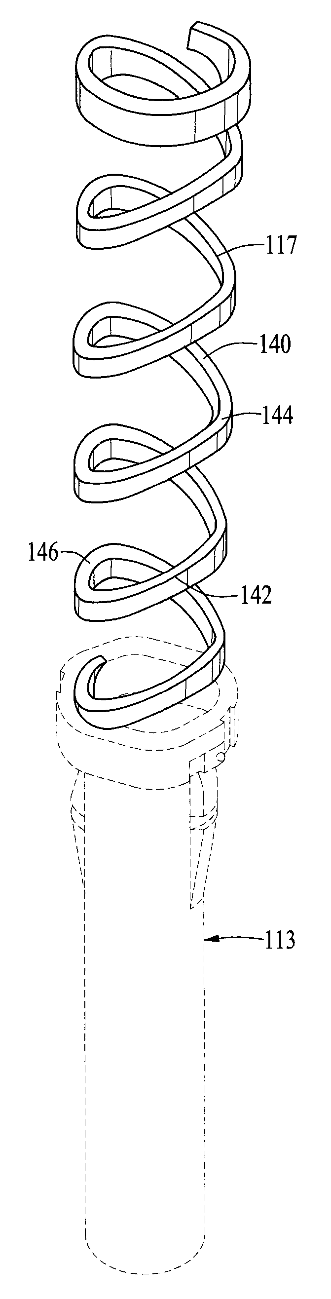
[0050]FIG. 13 illustrates a first embodiment of the sheath assembly 113 wherein the non-uniform helical spring 117 is integral with the sheath 114. FIGS. 4, 5 and 6 shows the same embodiment with the sheath and other portions of the safety syringes showed in the dotted lines. FIGS. 18-23 show several different views of the non-uniform spring portion 217 of the sheath assembly 213. In an alternative embodiment of the sheath assembly 213 the non-uniform helical spring 217 can be fabricated separate from the sheath 214 and the two components joined by known plastic joining techniques. FIGS. 24-32 show several different views of the non-uniform helical spring 217 as a separate component from the sheath 214. FIG. 32 is a cutaway side view showing the non-uniform helical spring 217 attached to the sheath 214. A preferred method of joining the spring 217 with the sheath 214 is to form the spring with flat top and bottom ends 218, 219, each end having an enlarged circumferential rim 220 on ...


PUM


Abstract

An improved safety hypodermic syringe includes a reciprocal tubular needle sheath disposed on the exterior of the syringe body, a latch mechanism engaging the syringe body and the sheath to latch the sheath in a needle-covering position after delivering contents from the syringe body, and a spring engaging the syringe body and the sheath and expandable to move the sheath to cover the needle point, where the spring is a non-uniform helical spring having multiple 360° turns each turn uniformly spaced from adjacent turns, each 360° turn comprising first and second alternating angled portions, the first of the alternating angled portions being at a first angle to a plane perpendicular to an axis through the center of the helical spring and the second angled portions being at a second lesser angle to the plane perpendicular to the axis.

Description

[0001]This invention relates to safety syringes and particularly to sliding sheaths moveable to cover needles on hypodermic syringes and has particular reference to the design of the spring and related components, the spring expanding to move the sheath forward, causing the sliding sheath to lock in a protective manner over the needle point or tip. The invention also relates to a unique configuration of a helical spring that has lesser turns and a greater strength when compressed than a comparable diameter prior art helical spring.BACKGROUND OF THE INVENTION[0002]This invention is an improvement on the sliding sheath mechanism and the spring design for repositioning the sheath of the general type shown in U.S. Pat. No. 5,057,086 granted Oct. 15, 1991, U.S. Pat. No. 5,279,584 granted Jan. 18, 1994 and U.S. Pat. No. 5,308,332 granted May 3, 1994 to John A. B. Dillard III and James A. Orr, said patents incorporated herein in their entirety.[0003]The prior Dillard et al. patents disclos...

Claims


Application Information

Patent Timeline
IPC IPC(8): A61M5/32F16F1/02
CPCA61M5/3148A61M5/3257A61M5/326A61M2005/3267A61M2005/3247F16F1/042A61M2005/3139
Inventor DILLARD, III, JOHN A. B.
Owner PROTECTUS MEDICAL DEVICES
Why Eureka
Try Eureka