Turbine disc with self-lubricating structure for micro gas turbine

A micro gas turbine and gas turbine technology, which is applied to gas turbine devices, mechanical equipment, engine components, etc., can solve problems such as the inability to control the air flow and air compression, the complex structure of the micro gas turbine, and the impact on use, and achieve simple structure and full combustion. Increase and improve the effect of utilization

Inactive Publication Date: 2021-02-05
杭州萧山技师学院
View PDF10 Cites 0 Cited by
  • Summary
  • Abstract
  • Description
  • Claims
  • Application Information

AI Technical Summary

Problems solved by technology

[0002] Micro gas turbines, as a newly developed small thermal generator, have excellent application prospects, and are considered to be likely to set off a technological innovation wave of "small power supply decentralization", thus becoming the mainstream of energy technology in the 21st century. Therefore, the market for micro There are certain requirements for gas turbines; however, the existing micro gas turbines are complex in structure and difficult to use. The air compression equipment in the existing micro gas turbines cannot control the air flow and air compression, which affects the use; After burning, most of them are discharged after passing through a simple heat exchanger, which has a certain impact on the environment. Therefore, it is very necessary to invent a turbine disk for a micro gas turbine with a self-lubricating structure.

Method used


Image

  • Turbine disc with self-lubricating structure for micro gas turbine
  • Turbine disc with self-lubricating structure for micro gas turbine
  • Turbine disc with self-lubricating structure for micro gas turbine

Examples


Embodiment Construction

[0020] The following will clearly and completely describe the technical solutions in the embodiments of the present invention with reference to the accompanying drawings in the embodiments of the present invention. Obviously, the described embodiments are only some, not all, embodiments of the present invention. Based on the embodiments of the present invention, all other embodiments obtained by persons of ordinary skill in the art without making creative efforts belong to the protection scope of the present invention.

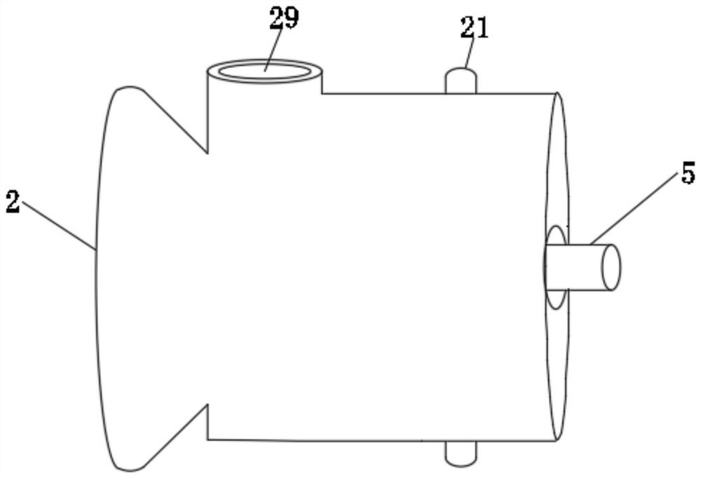
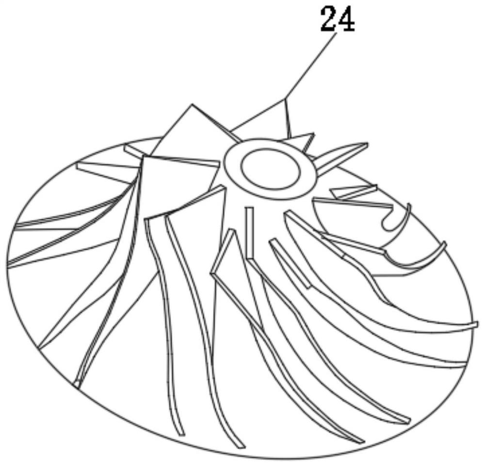
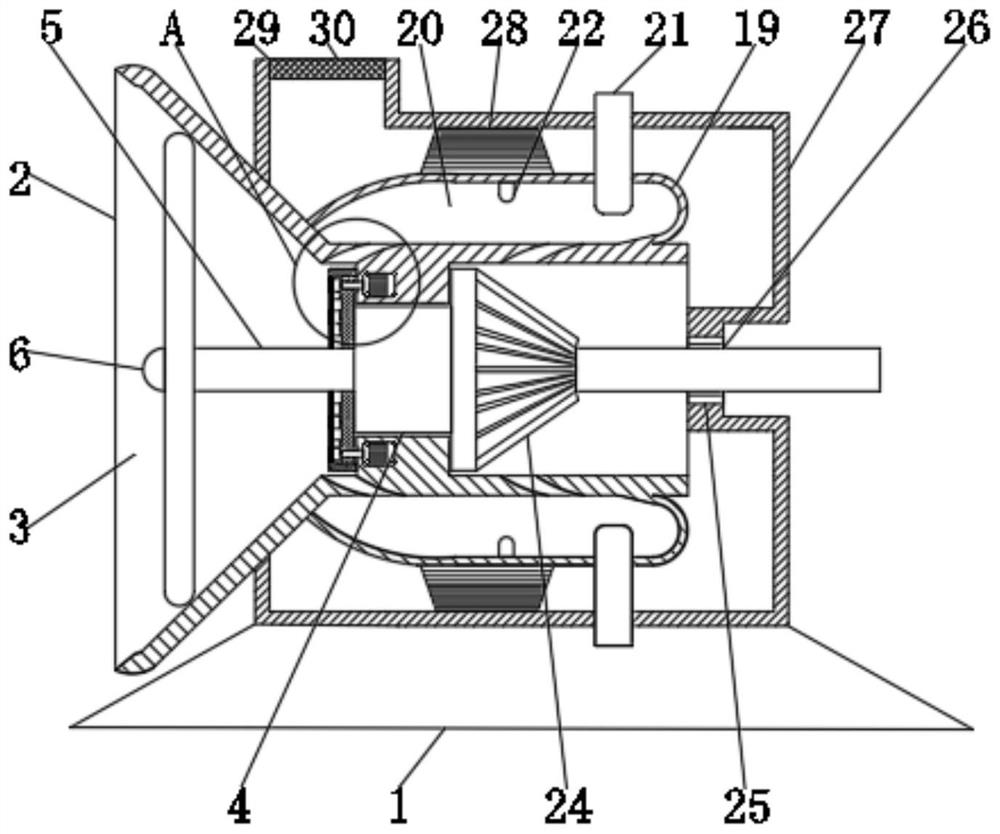
[0021] see Figure 1-6 , the present invention provides a technical solution: a turbine disk for a micro gas turbine with a self-lubricating structure, including a gas turbine frame 1, a gas turbine casing 2, an air inlet 3, a first bearing 4, a first rotating shaft 5, a fan 6. Motor 7, first limit disc 8, first rotating hole 9, second rotating shaft 10, first blade 11, driving gear 12, third rotating shaft 13, second blade 14, driven gear 15 , the second lim...


PUM


Abstract

The invention discloses a turbine disc with a self-lubricating structure for a micro gas turbine. The turbine disc comprises a gas turbine shell, a first rotating shaft, a motor, a first limiting disc, a first rotating hole, a second rotating shaft, a first blade, a driving gear, a third rotating shaft, a second blade, a driven gear, a second limiting disc, an inner gear, an air inlet, a combustion chamber, a fuel nozzle, an igniter, a turbine disc body, an exhaust pipe, a heat exchanger, an exhaust port and a filter screen. The turbine disc is simple in structure and convenient to use, through cooperation of the motor, the first limiting disc, the second rotating shaft, the first blade, the driving gear, the third rotating shaft, the second blade, the driven gear, the second limiting discand the inner gear, the structure is simple, and the purposes of controlling air flow and compressing the air are achieved through fine adjustment of the angle of the first blade and the angle of thesecond blade; and through cooperation of the exhaust pipe, the heat exchanger, the exhaust port and the filter screen, the influence on the external environment is reduced, and the using is convenient.

Description

technical field [0001] The invention relates to the technical field of micro gas turbine equipment, in particular to a turbine disk for a micro gas turbine with a self-lubricating structure. Background technique [0002] Micro gas turbines, as a newly developed small thermal generator, have excellent application prospects, and are considered to be likely to set off a technological innovation wave of "small power supply decentralization", thus becoming the mainstream of energy technology in the 21st century. Therefore, the market for micro There are certain requirements for gas turbines; however, the existing micro gas turbines are complex in structure and difficult to use. The air compression equipment in the existing micro gas turbines cannot control the air flow and air compression, which affects the use; After burning, most of them are discharged after passing through a simple heat exchanger, which has a certain impact on the environment. Therefore, it is very necessary t...

Claims


Application Information

Patent Timeline
Patent Type & Authority Applications(China)
IPC IPC(8): F02C3/04F02C7/042F02C7/057F01D5/00F01D25/30
CPCF01D5/00F01D25/30F02C3/04F02C7/042F02C7/057
Inventor 王尧林蒋金伟沈梁李林
Owner 杭州萧山技师学院
Why Eureka
Try Eureka