Cutting blade assembly for a mower

Inactive Publication Date: 2010-02-25
ABERNETHY RAYMOND ERIC
View PDF8 Cites 12 Cited by
  • Summary
  • Abstract
  • Description
  • Claims
  • Application Information

AI Technical Summary

Benefits of technology

[0022]The blade can have at least one baffle for producing upward air movement and/or at least one baffle for producing downward air movement. The baffles can be provided by upturned and downturned (twisted) regions of the blade. A distal end of the blade relative to the carrier can be upturn

Problems solved by technology

Disadvantages with bar-type cutters include that: cutting blades cannot be replaced independently of the carriers; they have to be balanced after sharpening one or more of the blades; and, damage can be caused to the drive shaft assembly, motor or deck when striking a foreign object during mowing.
Disadvantage

Method used


Image

  • Cutting blade assembly for a mower
  • Cutting blade assembly for a mower
  • Cutting blade assembly for a mower

Examples


Embodiment Construction

[0054]In the figures, like reference numerals refer to like features.

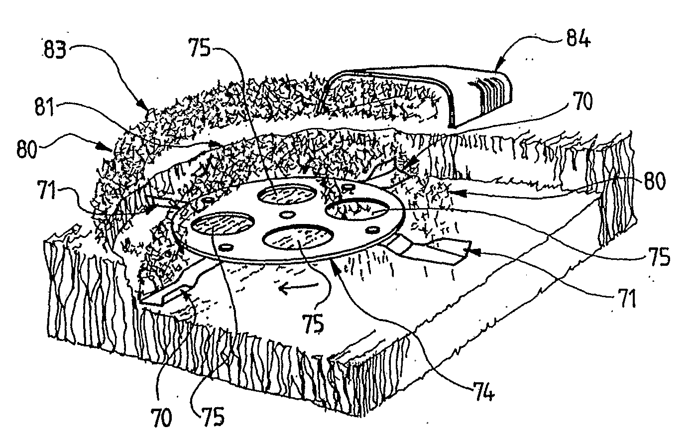
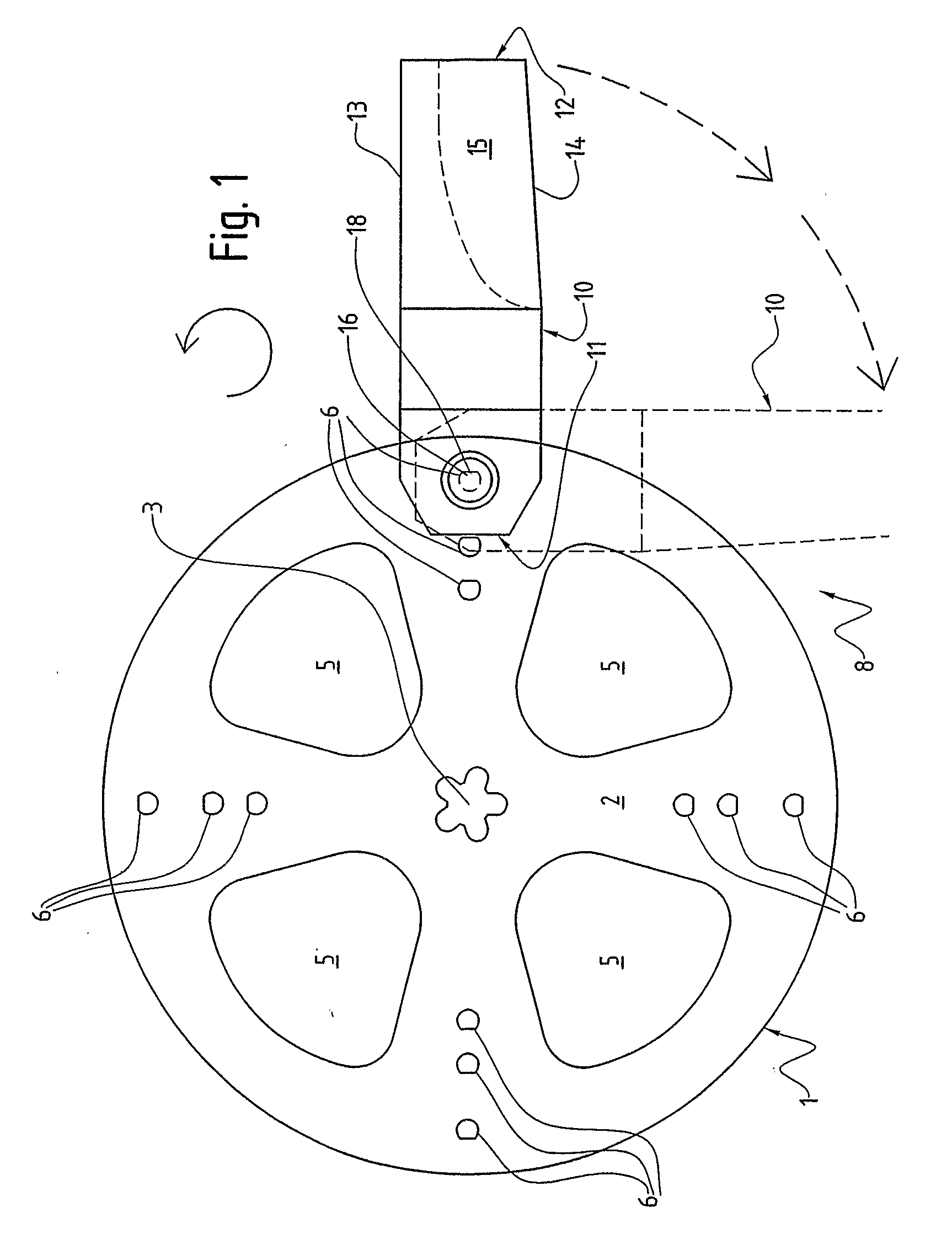
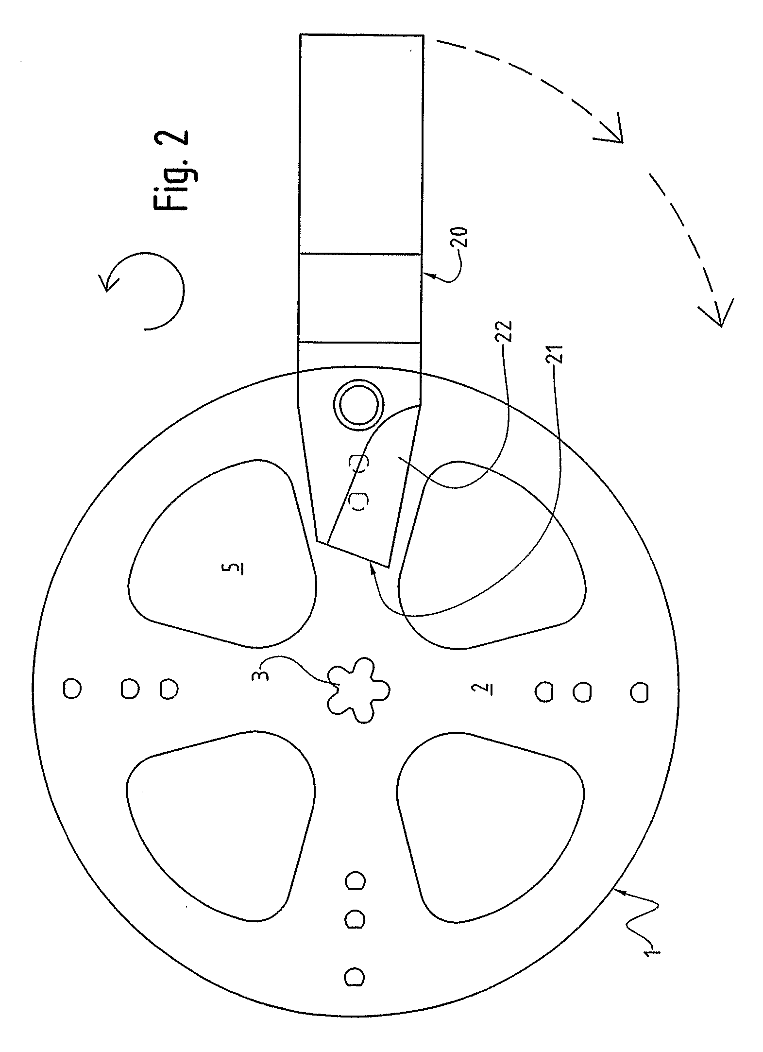
[0055]FIGS. 1 and 6 show a cutting blade assembly 8 for a rotational mower. The assembly 8 comprises a blade carrier 1 and four cutting blades 10 (only one of which is shown). The blade carrier 1 has a substantially planar discoid body 2, a mount 3 for mounting the body 2 to a drive shaft assembly (not shown) of the mower, four airflow passages 5 extending through the body 2, and a connecting mechanism 6 for connecting the blades 10 to the body 2.

[0056]The body 2 is made of laser-cut, high-strength steel (Bisplate 80™) having a thickness in the order of 5 to 6 mm.

[0057]The drive shaft connecting mechanism 3 comprises a star-shaped central aperture 3. A splined shaft of the drive shaft assembly is engageable with the central aperture 3. A bolt is extendable through the central aperture 3 and within a threaded interior of the shaft to hold the shaft and body 2 together.

[0058]The blade 10 is made of high-strength stee...


PUM

PropertyMeasurementUnit
Thicknessaaaaaaaaaa
Thicknessaaaaaaaaaa
Shapeaaaaaaaaaa

Abstract

A cutting blade assembly (8) for a rotary mower. The assembly (8) comprises a blade carrier (1) and four swing-back cutting blades (10) (only one of which is shown). The blade carrier (1) has a substantially planar discoid body (2), a mount (3) for mounting the body (2) to a drive shaft assembly (not shown) of the mower, four airflow passages (5) extending through the body (2), and a blade connecting mechanism (6) for connecting the blades (10) to the body (2). The body (2) is made of laser- or plasma-cut, high-strength steel (Bisplate 80™) having a thickness in the order of 5 to 6 mm.

Description

TECHNICAL FIELD[0001]This invention relates to blade carriers, cutting blades and cutting blade assemblies for rotary mowers.BACKGROUND ART[0002]Rotary mowers typically have a deck and two or more cutting blades rotatable within the deck. The blades usually extend from opposing sides of a blade carrier of the mower. A drive shaft assembly, which is either directly or indirectly coupled to a motor of the mower, is connected to the blade carrier. Some mowers, such as ride-on mowers, have two or more decks and / or drive shafts.[0003]For some types of mowers the cutting blades and blade carrier are of unitary construction. This is the case with bar-type cutters which have blades at opposing ends of a bar-shaped blade carrier. Disadvantages with bar-type cutters include that: cutting blades cannot be replaced independently of the carriers; they have to be balanced after sharpening one or more of the blades; and, damage can be caused to the drive shaft assembly, motor or deck when striking...

Claims


Application Information

Patent Timeline
IPC IPC(8): A01D34/00A01D34/73B23P11/00
CPCA01D34/733Y10T29/49826A01D2101/00A01D34/736
Inventor ABERNETHY, RAYMOND ERIC
Owner ABERNETHY RAYMOND ERIC
Why Eureka
Try Eureka