Method for detecting a traffic space

a technology of traffic space and detection method, which is applied in the field of traffic space detection, can solve the problems of not being able to distinguish whether a distant object is moving quickly, not being able to make the distinction of real-time speed, and proposals that are neither real-time capable nor robust enough for automotive engineering applications, so as to achieve better detection

Inactive Publication Date: 2010-02-25
ROBERT BOSCH GMBH
View PDF11 Cites 15 Cited by
  • Summary
  • Abstract
  • Description
  • Claims
  • Application Information

AI Technical Summary

Benefits of technology

[0013]The approach of the exemplary embodiments and / or exemplary methods of the present invention having the features described herein avoids the disadvantages of the known approaches. It is real-time capable and robust and is therefore suitable in a particular manner for automotive engineering applications having rapidly changing image content. As future driver assistance systems are intended to provide the driver not only with an image of the vehicle surroundings but are also intended to convey additional information and warnings, the system according to the present invention is in particular well suited for use in such systems. Namely, it makes possible the detection of static and moved obstructions from the image flow and the segmentation of the image into roads, static and moved objects of interest, and other features. In a manner which is advantageous in particular, for example, warning signs may be detected as static objects in the images. It is thus possible to parameterize a lane detection function of the driver assistance system in order to be better able to detect a construction site situation which is critical in particular. Furthermore, reflector posts detected as static objects are capable of advantageously supporting a lane guidance function of the driver assistance system if no easily detectable markings are present on the road surface. The detection of moving objects and their insertion into the display observed by the driver make a warning possible which is effective in particular even in poor visibility conditions, in particular when driving at night. Based on a flow analysis, the segmented road course makes an exact determination of the vehicle's own movement possible. This makes it possible to support the measuring accuracy of other on-board sensors. For example, it is thus possible to compensate for drift in a yaw rate sensor. In a manner which is advantageous in particular, the exemplary embodiments and / or exemplary methods of the present invention may also be used to detect the condition of the terrain along the road surface based on a model. For example it is thus possible to detect if a ditch runs along the edge of the road surface or if the road is bordered by a steep slope. In an evasion maneuver which may be necessary, these facts may be of great significance in estimating the risk of such a maneuver. This will result in valuable additional functions for future driver assistance systems. For example, the terrain profile adjacent to the road surface may be taken into consideration for the support function LDW (lane departure warning) or for an evasion recommendation in the case of danger.
[0014]Furthermore, the system of the present invention may also be used advantageously in highly advanced passenger protection systems having a precrash function. Of course, the exemplary embodiments and / or exemplary methods of the present invention may also be used with cameras positioned on the side or the rear of the vehicle in order to detect images from these areas of the vehicle surroundings.
[0015]Exemplary embodiments of the present invention are explained in greater detail below with reference to the drawing.

Problems solved by technology

However, because mono cameras provide only a two-dimensional image of the vehicle surroundings, three-dimensional structures cannot be readily extracted from the video signals provided by the mono camera.
However, such a measurement is precise only when scaling is not taken into account.
For example, it is not readily possible to make the distinction of whether a distant object is moving rapidly or a close object is moving slowly, since both objects leave the same information on the image sensor.
Most of these proposals are neither real-time capable nor robust enough for automotive engineering applications.

Method used


Image

  • Method for detecting a traffic space
  • Method for detecting a traffic space
  • Method for detecting a traffic space

Examples


Embodiment Construction

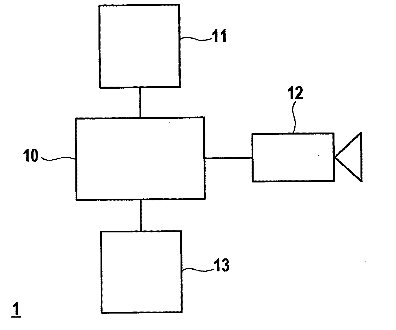
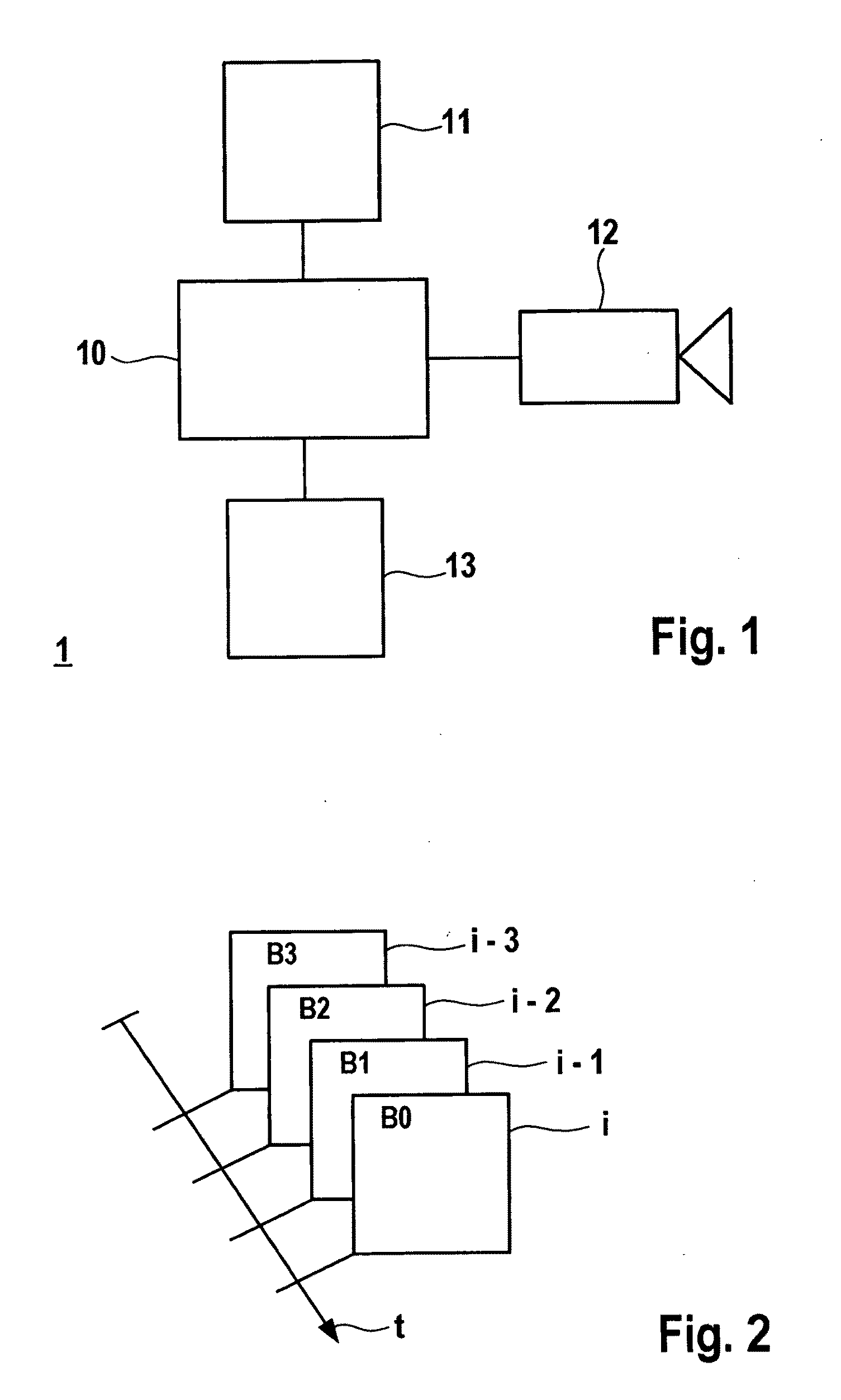
[0031]The exemplary embodiments and / or exemplary methods of the present invention is used in a driver assistance system which is provided in a motor vehicle for the support of the driver. FIG. 1 shows a simplified schematic block diagram of such a driver assistance system. Driver assistance system 1 includes at least one monocular image sensor 12 for detecting the traffic space traveled by the motor vehicle. This image sensor 12 is, for example, a camera based on CCD technology or CMOS technology. In addition to image sensor 12, numerous additional sensors may be provided, for example radar / lidar or ultrasound sensors which, however, are not shown in detail in FIG. 1 but instead are represented by the block diagram. Image sensor 12 is connected to a control unit 10. The additional sensors (block 11) are also connected to control unit 10. Control unit 10 processes the signals of the sensors.

[0032]Also connected to control unit 10 is a function module which in particular connects driv...


PUM


Abstract

A method is described for detecting a traffic space comprising a driver assistance system including a monocular image sensor. The image sensor produces chronologically successive images of the traffic space. The images of the image sequence are used to ascertain the visual flow and examine it for discontinuities. Discontinuities found in the visual flow are assigned to objects in the traffic space.

Description

FIELD OF THE INVENTION[0001]The present invention relates to a method for detecting a traffic space.BACKGROUND INFORMATION[0002]Methods for detecting the traffic space using image sensors assigned to driver assistance systems are being used in modern vehicles to an increasing extent. Such driver assistance systems support the driver, for example in maintaining the selected lane, in making an intended lane change, in maintaining the safety distance from preceding vehicles, and while driving in poor visibility conditions, for example at night or in bad weather. Frequently, assistance functions such as LDW (lane departure warning), LKS (lane keeping support), LCA (lane change assistant) and ACC (automatic (adaptive) cruise control) are implemented. In order to detect the vehicle surroundings, at least one image sensor is provided in such a driver assistance system. A video camera based on CCD or CMOS technology may be used as an image sensor, the video camera typically being installed ...

Claims


Application Information

Patent Timeline
Patent Type & Authority Applications(United States)
IPC IPC(8): H04N5/222B60Q1/00
CPCG06T7/2006G06T7/215
Inventor STEIN, FRIDTJOF
Owner ROBERT BOSCH GMBH
Why Eureka
Try Eureka