Manipulation input apparatus

a technology of input apparatus and input input, which is applied in the direction of static indicating device, dashboard fitting arrangement, instruments, etc., can solve the problem of restricting the manipulation mode of the touch panel, and achieve the effect of increasing the manipulation mod

Inactive Publication Date: 2010-02-25
DENSO CORP
View PDF7 Cites 56 Cited by
  • Summary
  • Abstract
  • Description
  • Claims
  • Application Information

AI Technical Summary

Benefits of technology

[0013]The present invention is made in consideration of the above problem. It is thus an object to provide a manipulation input apparatus to improve manipulation modes in which a touch manipulation is applied to a panel member for receiving touch manipulation inputs.
[0015]In the above manipulation input apparatus, the structural section is provided to able to apply an outward load (e.g., an upward load if the panel member is arranged horizontally) against the outside surface or front surface of the panel member whose outside surface functions as a manipulation input surface for receiving a touch manipulation input. Thus, the outward load (−Z direction) can be applied using or via the structural section; the load having the direction in which the panel member is pulled outward can be detected by the load detection section. That is, the above manipulation input apparatus allows the detection of the two directional loads, namely, both the load pressing inward the panel member (load of +Z direction) and the load pulling outward the panel member. Thereby, the load information of the ±Z directions can be effectively used, increasing the manipulation modes in the panel member.

Problems solved by technology

As a result, the conventional manipulation input apparatuses typically use only the depression load (+Z direction) against the touch panel member substantively, thus tending to restrict manipulation modes in the touch panel member.

Method used


Image

  • Manipulation input apparatus
  • Manipulation input apparatus
  • Manipulation input apparatus

Examples


first embodiment

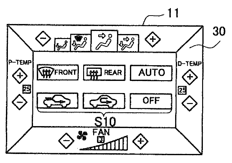
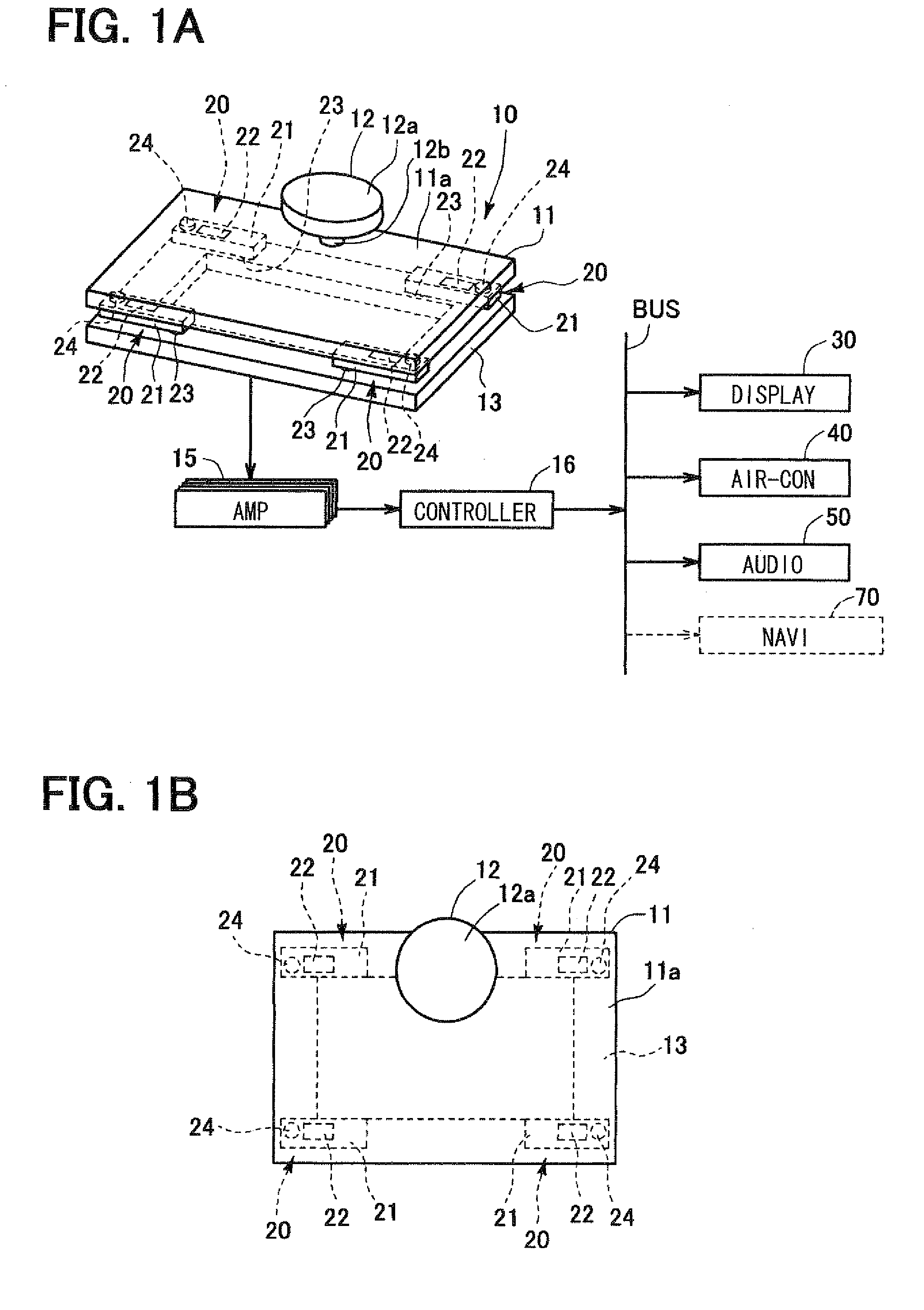
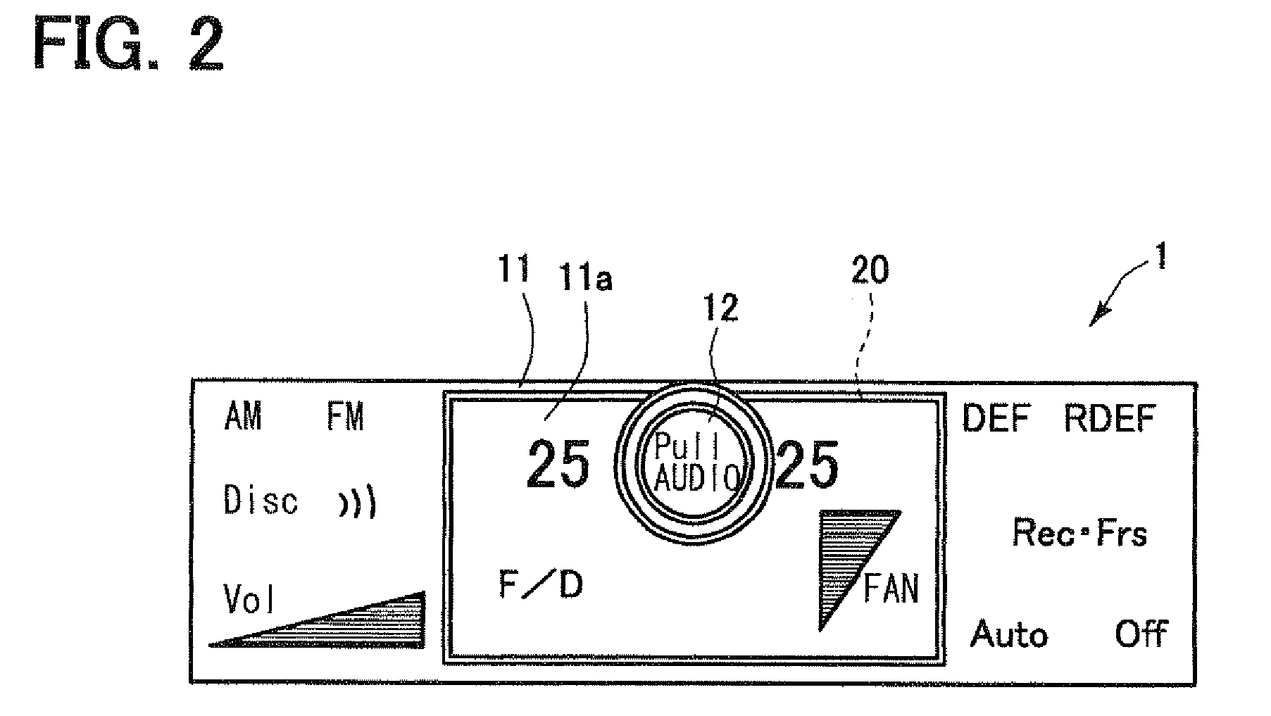
[0046]The following describes an embodiment of the present invention with reference to drawings. FIG. 1A illustrates an overall configuration of a manipulation input apparatus 10 according to a first embodiment of the present invention. This manipulation input apparatus 10 is applicable to an operation panel 1 provided in an instrument panel of a vehicle, for example, as illustrated in FIG. 2. The operation panel 1 is used for operating an air-conditioner 40 and an audio apparatus 50.

[0047]The manipulation input apparatus 10 is provided with a panel member 11, a stick 12, a frame 13, and strain gauge type sensors 20, as illustrated in FIGS. 1A and 1B. In FIG. 1A, the upper side corresponds to the front side (i.e., front surface) or outside (i.e., outside surface) of the manipulation input apparatus 10 while the lower side corresponds to the rear side or inside of the manipulation input apparatus 10. The front side signifies the side facing a user or operator of the manipulation inpu...

second embodiment

[0087]In the above first embodiment and its modification, the manipulation input apparatus 10 is applied to the operation panel 1, which is provided in the instrument panel of the vehicle; the display section 30 is arranged inside of the frame 13. Alternatively, the manipulation input apparatus 10 can be applied to a remote operation apparatus as a remote input section 2 (also referred to as a remote operation device 2). The remote operation apparatus includes the remote input section 2 and a display section 30, which is arranged in a central portion of the instrumental panel of the vehicle separately from the manipulation input apparatus 10 (i.e., remote input section 2) as illustrated in FIG. 11. While seeing the display section 30 in the instrument panel, an operator performs a remote operation using the manipulation input apparatus 10, positioned at hand of the user or driver in the vehicle.

[0088]The remote operation device 2 is arranged at a center console C inside the compartm...

third embodiment

[0094]In the above first and second embodiments, the stick 12 is provided in the manipulation input surface 11a of the panel member 11 as the structural section. Instead of such a stick 127 for example, a bias member or bias mechanism 120 may be provided as shown in FIGS. 13A, 13B. Furthermore, the other configuration is almost comparable to that of the above first embodiment.

[0095]The bias mechanism 120 is provided with a dialing portion 121 and a pressing portion 122. The pressing portion 122 is attached to the dialing portion 121 at one end while abutting to the rear surface of the panel member 11 at the other end, thereby resiliently pressing up the panel member 11 towards the manipulation input surface 11a, i.e., towards the outside of the manipulation input surface 11a.

[0096]The dialing portion 121 includes as one body unit a cylindrical dial 121a and a shaft 121b, which is extended downward from the lower surface of the dial 121a. The dialing portion 121 passes through an op...


PUM


Abstract

A manipulation input apparatus includes a panel member, strain gauges, and a controller. The panel member has a front surface functioning as a manipulation input surface to which an input is executed by touch manipulation. The strain gauges detect a load which is applied to the panel member. The controller calculates a position to which a load is applied based on load detection result by the strain gauges. A stick as a convex-shaped structural section is further arranged and integrated in the manipulation input surface of the panel member such that an upward load against the panel member is applied via the stick.

Description

CROSS REFERENCE TO RELATED APPLICATION[0001]The present application is based on and incorporates herein by reference Japanese Patent Applications No. 2008-212693 filed on Aug. 21, 2008, No. 2008-246262 filed on Sep. 25, 2008, and No. 2008-251784 filed on Sep. 29, 2008.FIELD OF THE INVENTION[0002]The present invention relates to a manipulation input apparatus having a panel member for receiving a touch manipulation.BACKGROUND OF THE INVENTION[0003][Patent document 1] JP-H5-298013 A[0004][Patent document 2] JP-H7-298013 A[0005][Patent document 3] JP-H7-319618 A (corresponding to U.S. Pat. No. 5,877,749)[0006][Patent document 4] JP-2001-43011 A (corresponding to U.S. Pat. No. 6,360,622)[0007][Patent document 5] JP 2002-157063 A[0008][Patent document 6] JP-2006-126997 A[0009][Patent document 7] JP-2006-252093 A[0010]Patent documents 1 to 6 describe manipulation input apparatuses for in-vehicle apparatuses such as a car navigation apparatus. In manipulation input apparatuses, a load of m...

Claims


Application Information

Patent Timeline
Patent Type & Authority Applications(United States)
IPC IPC(8): G06F3/041G06F3/033
CPCB60H1/00985B60K37/06G01C21/36G06F3/0338B60K2350/102G06F3/0418B60K2350/1024B60K2350/104G06F3/0414B60K2370/126B60K2370/143B60K2370/145
Inventor HISATSUGU, SHINSUKEITOH, MASAHIRONAKANISHI, KAZUNOBU
Owner DENSO CORP
Why Eureka
Try Eureka