Liquid crystal display apparatus, liquid crystal display apparatus driving circuit, liquid crystal display apparatus source driver, and liquid crystal display apparatus controller

a technology of liquid crystal display and driving circuit, which is applied in the direction of electric digital data processing, instruments, computing, etc., can solve the problems of flicker phenomenon, uneven center values (center potentials), and greatly impaired balance between positive negative polarity gray scale voltage. achieve the effect of reducing flicker phenomenon

Inactive Publication Date: 2010-02-25
SHARP KK
View PDF15 Cites 26 Cited by
  • Summary
  • Abstract
  • Description
  • Claims
  • Application Information

AI Technical Summary

Benefits of technology

[0015]The aforementioned conventional two flicker phenomena are fundamentally different from each other in view of the factor, but the aforementioned flicker phenomena are caused by the deviation between the charge pull-in amounts ΔV in the display screen of the liquid crystal panel. Thus, it is possible to reduce the flicker phenomenon by adjusting a value of a gray scale voltage applied to the liquid crystal layer in accordance with the deviation between the charge pull-in amounts ΔV in the display screen of the liquid crystal panel.

Problems solved by technology

Further, a conventional liquid crystal display apparatus driving circuit allows for such adjustment that the flicker phenomenon at a certain point of the panel screen will not be viewed with eyes.
Thus, in case where the adjustment is performed at the center of the panel for example, the balance between the positive polarity gray scale voltage and the negative polarity gray scale voltage is greatly impaired at the left and right sides of the panel, that is, the center values (center potentials) become uneven, so that the flicker phenomenon occurs.
There is such a problem that the change of the charge pull-in amounts causes deterioration of the flicker phenomenon.

Method used


Image

  • Liquid crystal display apparatus, liquid crystal display apparatus driving circuit, liquid crystal display apparatus source driver, and liquid crystal display apparatus controller
  • Liquid crystal display apparatus, liquid crystal display apparatus driving circuit, liquid crystal display apparatus source driver, and liquid crystal display apparatus controller
  • Liquid crystal display apparatus, liquid crystal display apparatus driving circuit, liquid crystal display apparatus source driver, and liquid crystal display apparatus controller

Examples


embodiment 1

(Flicker Phenomenon)

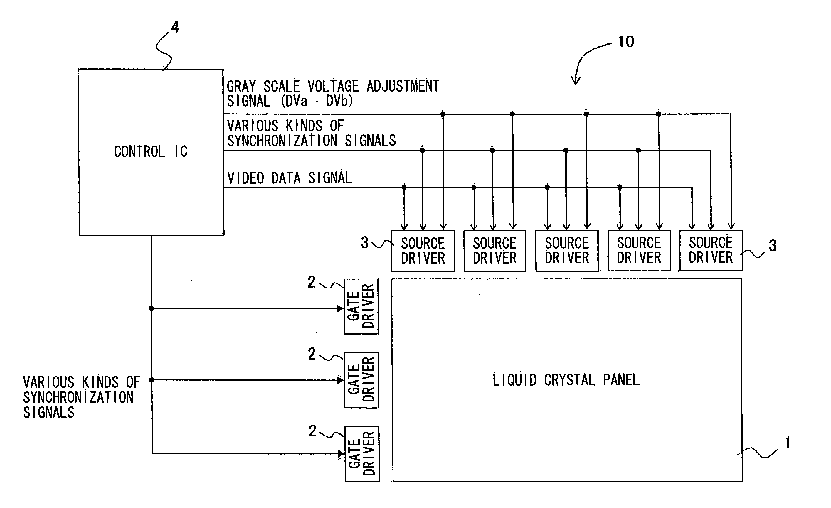
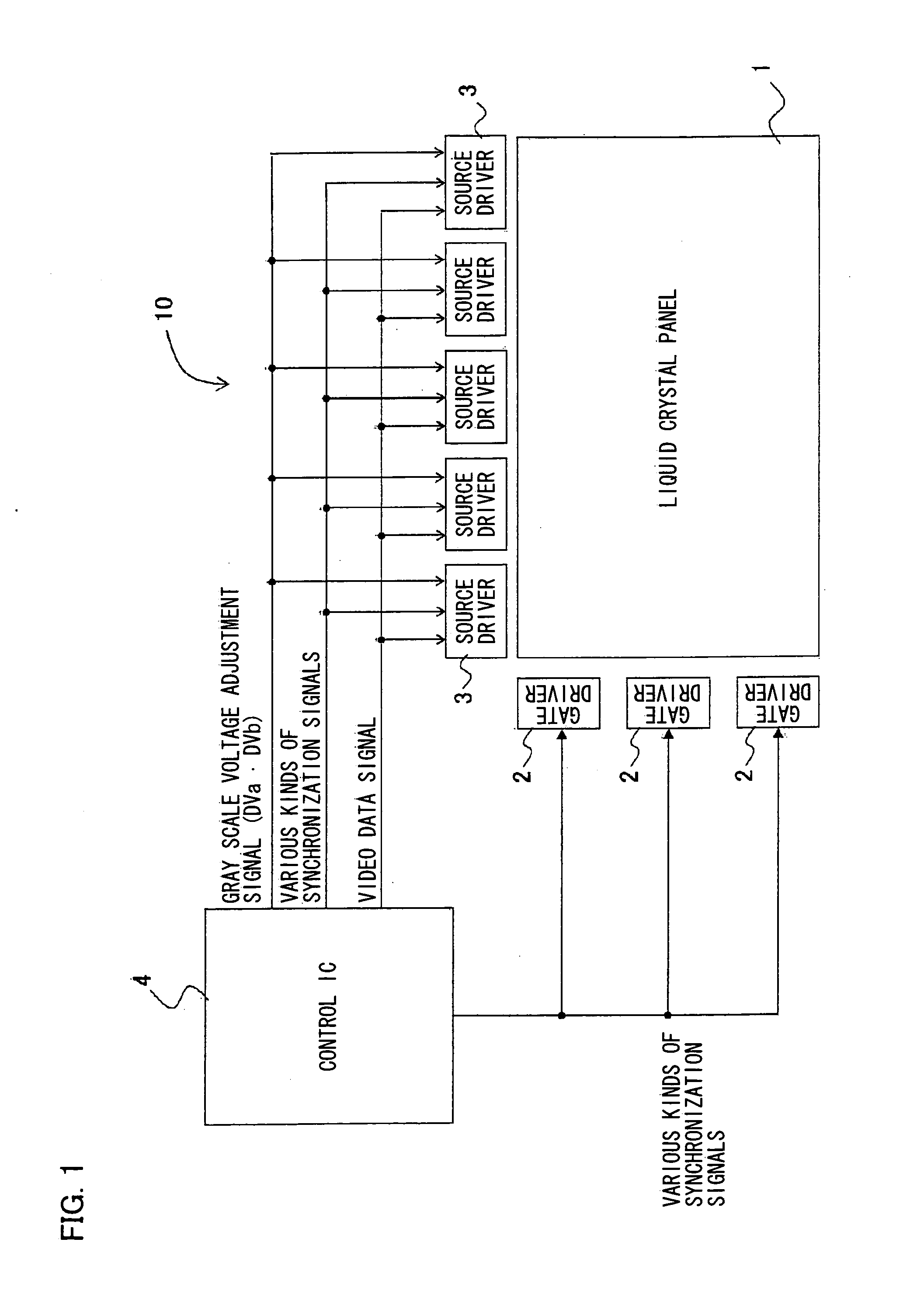
[0072]A liquid crystal display apparatus of an embodiment of the present invention includes driving sections (source drivers) each of which aims to solve a flicker phenomenon. First, the following describes the flicker phenomenon before describing the present embodiment.

[0073]The flicker is caused by the following two factors.

[0074]The first factor is as follows. Due to a round waveform of a gate driving signal in a TFT liquid crystal panel, charge pull-in amounts ΔV respectively caused by parasitic capacitances Cgd of pixels of a TFT liquid crystal substrate are different from each other.

[0075]The second factor is as follows. In the step of forming a pixel pattern on the TFT liquid crystal substrate, an area size of the TFT liquid crystal substrate may be so large that it is difficult to form the pixel pattern on the entire surface of the TFT liquid crystal substrate by a single forming process, so that the forming process of the pixel pattern is performed plura...

embodiment 2

[0176]Another embodiment of the present invention is described as follows. The present embodiment describes only differences from Embodiment 1 and descriptions of the same configuration will be omitted here.

[0177]The charge pull-in amounts ΔV are deviated in the panel screen, and also gray scale voltage values applied to a drain region of the TFT are deviated (deviation of gray scale voltages). Generally, this deviation is referred to as “ω value”.

[0178]As in Embodiment 1, it is possible to reduce the flicker phenomenon by increasing / adjusting gray scale voltages VH0a, VH63a, VL0a, and VL63a so that each increment / adjustment corresponds to the same adjustment voltage Va (also by increasing / adjusting gray scale voltages VH0b, VH63b, VL0b, and VL63b so that each increment / adjustment corresponds to the same adjustment voltage Va). Also, it is possible to further reduce the flicker phenomenon by correcting the c value with a highly free gray scale voltage adjustment function.

[0179]Thus,...

embodiment 3

[0212]Next, still another embodiment of the present invention is described as follows.

[0213]As in Embodiment 2, descriptions of the same configuration as those of Embodiments 1 and 2 will be omitted here.

[0214]In Embodiment 3, each source driver 3 includes two adjustment voltage generation circuits, i.e., the adjustment voltage generation circuits 40a and 40b. Meanwhile, in the present embodiment, each source driver 3 includes an adjustment voltage generation circuit (third gray scale voltage generation circuit) 40c as illustrated in FIG. 13. More specifically, the adjustment voltage generation circuit 40c is provided only on the right end (or the left end) of the source driver 3.

[0215]The following describes the case where the adjustment voltage generation circuit 40c is provided only on the right end of the source driver 3.

[0216]In this case, a second source driver 3 provided on the right side of a first source driver 3 receives an output (Vd; fourth output adjustment voltage) fro...


PUM


Abstract

In one embodiment of the present invention, a liquid crystal display apparatus driving circuit selectively supplies positive polarity gray scale voltages or negative polarity gray scale voltages to video signal lines as video signals. The circuit includes a gray scale voltage generation circuit for generating a gray scale voltage for display; and first and second gray scale voltage adjustment sections included in the circuit, for increasing positive and negative polarity gray scale voltages while maintaining a voltage difference between the positive and negative polarity gray scale voltages and respectively adjust a center potentials of the positive and negative polarity gray scale voltages. This makes it possible to provide the liquid crystal display apparatus driving circuit which can make the center values of the positive and negative polarity gray scale voltages proximate to values which makes it possible to further reduce the flicker phenomenon without changing the gray scale property.

Description

TECHNICAL FIELD [0001]The present invention relates to (i) a liquid crystal display apparatus of an active matrix type etc. used in a display screen such as a display of a television apparatus and a monitor of a personal computer for example, and further to (ii) a liquid crystal display apparatus driving circuit, (iii) a liquid crystal display apparatus source driver, and (iv) a liquid crystal display apparatus controller, which are used for the liquid crystal display apparatus.BACKGROUND ART [0002]Conventionally, a liquid crystal display apparatus includes a liquid crystal panel in which: a plurality of scanning signal lines (gate signal lines) and a plurality of video signal lines (source signal lines) intersect with each other, and there are provided in a matrix manner a plurality of display pixels each of which is connected to the gate signal line and the source signal line so as to correspond to each of regions sectioned by both the lines. Each display pixel has: a liquid cryst...

Claims


Application Information

Patent Timeline
Patent Type & Authority Applications(United States)
IPC IPC(8): G09G5/10
CPCG02F2001/133397G02F2203/30G09G3/3614G09G3/3685G09G2320/0276G09G2320/0204G09G2320/0223G09G2320/0233G09G2320/0247G09G3/3696G02F1/133397
Inventor HIGASHINO, HIROYUKI
Owner SHARP KK
Why Eureka
Try Eureka