Drive transmission device and ink jet recording apparatus

Active Publication Date: 2010-02-25
CANON KK
View PDF8 Cites 14 Cited by
  • Summary
  • Abstract
  • Description
  • Claims
  • Application Information

AI Technical Summary

Benefits of technology

[0011]An object of the present invention is to provide a drive transmission device and an ink jet recording apparatus capable of achievin

Problems solved by technology

However, the above construction cannot properly perform the drive transmission if there are more than two drive transmission destinations.
However, bi-directional rotational drive force in both normal and reverse rotation direc

Method used


Image

  • Drive transmission device and ink jet recording apparatus
  • Drive transmission device and ink jet recording apparatus
  • Drive transmission device and ink jet recording apparatus

Examples


first exemplary embodiment

[0038]The description of an ink jet recording apparatus mounting thereon a drive transmission device according to the first exemplary embodiment will be provided.

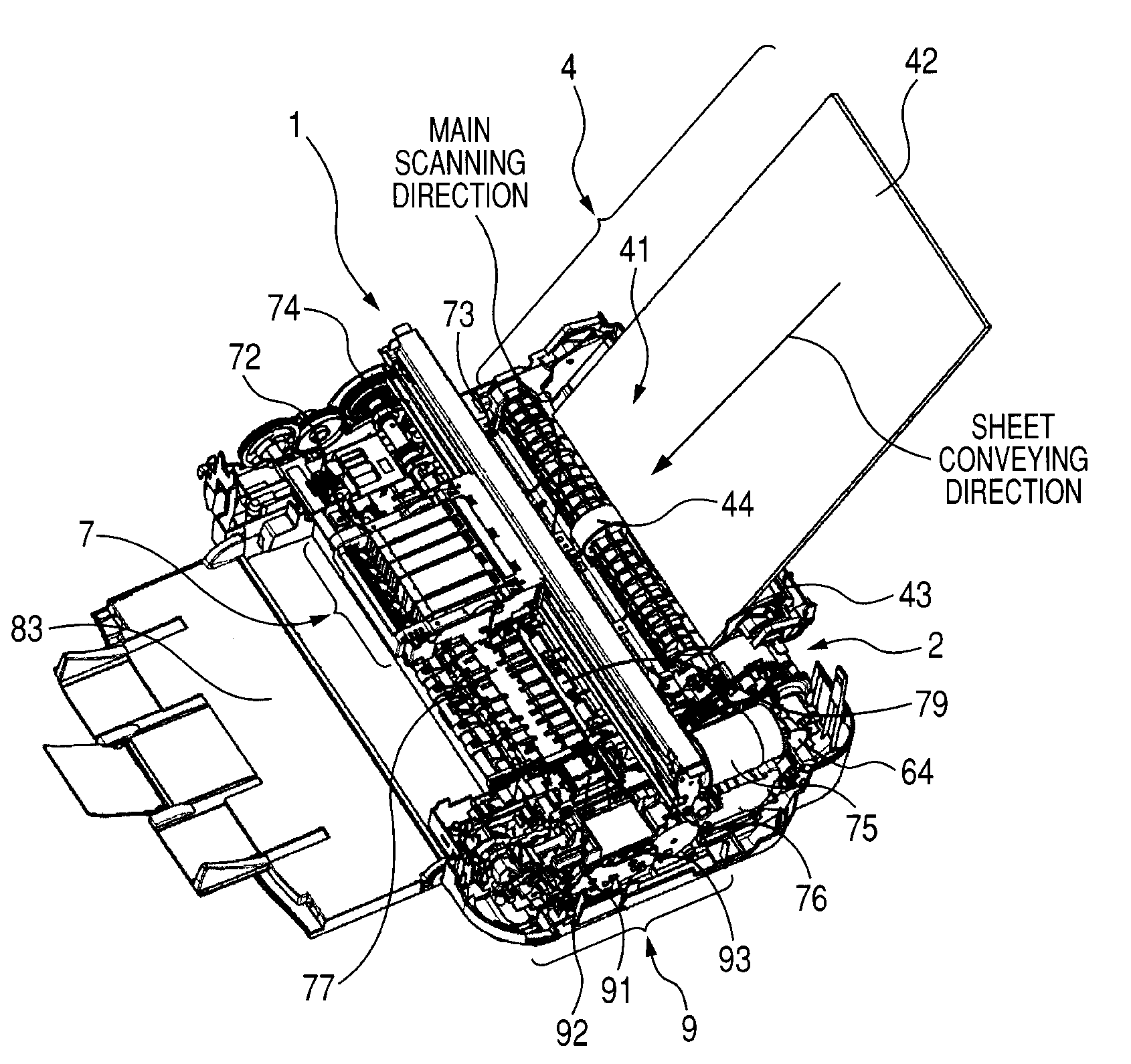
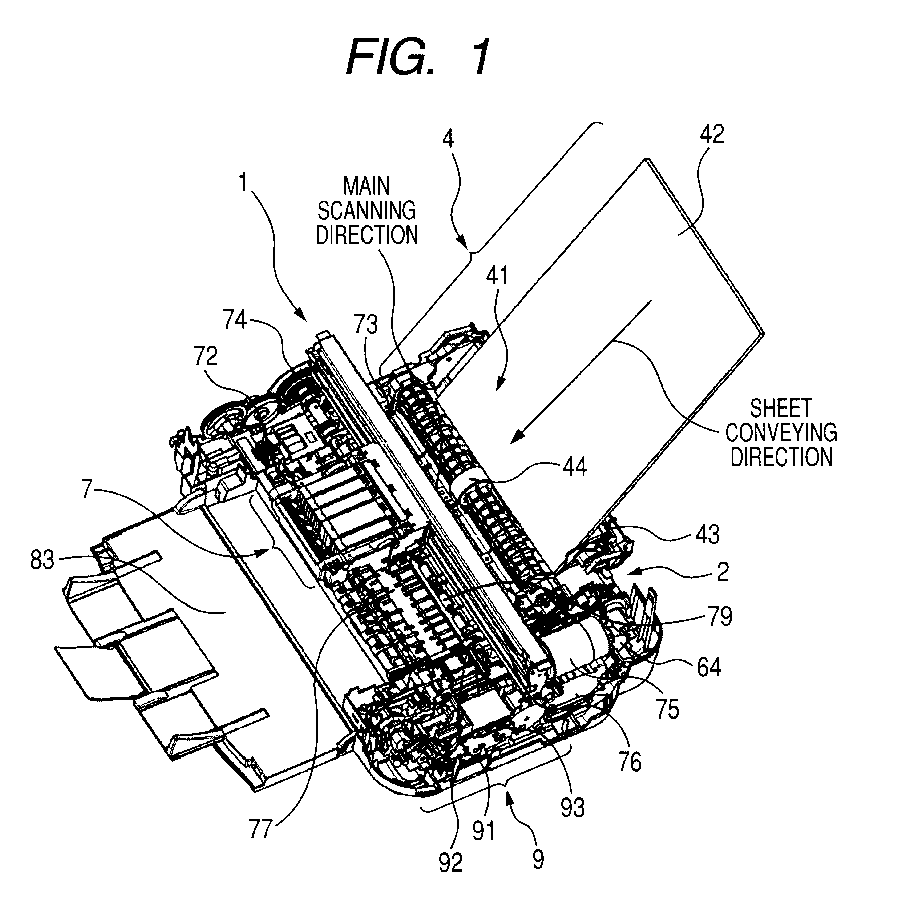
[0039]First, the description of the simplified construction of the ink jet recording apparatus 1 will be provided with reference to FIGS. 1 to 2. FIG. 1 is a perspective view illustrating the simplified construction of the ink jet recording apparatus, and FIG. 2 is a sectional view illustrating the simplified construction of the ink jet recording apparatus.

[0040]Sheets 42 as a recording medium are staked and held in a feeding opening 41 of a feeding mechanism 4. The sheets 42 are stacked on a pressure plate 43 which is provided on the lower portion of the feeding opening 41. A feeding roller 44 is disposed on an opposite side of the pressure plate 43, and the pressure plate 43 is urged toward the feeding roller 44 by a non-illustrated pressure plate spring. A separation roller 45 is also urged toward the feeding roller 44 b...

second exemplary embodiment

[0093]Next, the description of the second exemplary embodiment will be provided with reference to FIGS. 14 and 17. FIG. 14 is a flowchart for describing the operation for switching drive transmission to the feeding position B according to the second exemplary embodiment; and FIG. 17 is a view illustrating a state where the riding state of the planetary gear 22 is eliminated in the drive transmission switching mechanism 2.

[0094]The construction of the ink jet recording apparatus 1 and the drive transmission switching mechanism 2 is the same as the construction of the first exemplary embodiment. The operations in steps S41 to S45 illustrated in FIG. 12 are the same as those of steps S61 to S65 illustrated in FIG. 14. The difference between the first exemplary embodiment and the second exemplary embodiment lies in the operations in steps S71 to S79 in FIG. 14; therefore, only the different operations will be described and the descriptions of the same operations will be omitted.

[0095]As...


PUM


Abstract

In the revolving restricted state, the planetary gear meshes with the drive input gear, and the clutch mechanism is unable to transmit the rotational drive force; in the freely revolvable state, the planetary gear is separated apart from the drive input gear, and the clutch mechanism is able to transmit the rotational drive force, the drive transmission switching mechanism is provided with first and second abutting portions which are configured to come into contact with the planetary arm rotated in the freely revolvable state so as to initialize the revolving position of the planetary gear, and the drive transmission switching mechanism is capable of selecting which one of the first and second abutting portions will come into contact with the planetary arm in accordance with the position of the drive input gear transmitting the rotational drive force among the plurality of drive input gears.

Description

BACKGROUND OF THE INVENTION[0001]1. Field of the Invention[0002]The present invention relates to a drive transmission device that uses a planetary gear mechanism. The present invention also relates to an ink jet recording apparatus that discharges ink on a recording medium, thereby performing recording by using such a drive transmission device.[0003]2. Description of the Related Art[0004]Hitherto, recording apparatuses have been known which include a feeding mechanism for feeding a sheet as a recording medium to the inside thereof, a conveying mechanism for conveying the fed sheet, a recording mechanism for recording data or images on the fed sheet, and a discharge mechanism for discharging the recorded sheet outside the recording apparatus. The recording apparatuses are also provided with a drive source for operating the respective mechanisms and a drive transmission mechanism.[0005]Among such recording apparatuses, ink jet recording apparatuses include a recording head as the reco...

Claims


Application Information

Patent Timeline
IPC IPC(8): B41J29/38F16H3/44
CPCB41J23/025
Inventor TOKI, NOBUHIRO
Owner CANON KK
Why Eureka
Try Eureka