Detecting illuminant flicker

a technology of illuminant and flicker, which is applied in the field of image processing using a digital sensor array, can solve the problems of poor indication, computational cost of task of acquiring frame difference data, and conventional approaches such as those just cited, and achieves improved identification ability, high dynamic range, and efficient use of processing resources.

Inactive Publication Date: 2010-02-25
INTELLECTUAL VENTURES FUND 83 LLC
View PDF18 Cites 38 Cited by
  • Summary
  • Abstract
  • Description
  • Claims
  • Application Information

AI Technical Summary

Benefits of technology

[0043]Advantages of the present invention include improved ability to identify illuminant flicker under difficult conditions, such as when scene content has high dynamic range and has scene content masking the illuminant banding. It also makes efficient use of processing resources. Using autocorrelation is well adapted to handle situations where the exposure bands are periodic but not precisely sinusoidal.

Problems solved by technology

Conventional approaches such as those just cited have several limitations.
In practice, frame differences provide a poor indication of variation in exposure, particularly when these values are applied to linear image sensor data and the task of acquiring frame difference data can be computationally costly.
Ratios of linear data provide a more sensitive result, but computational division is also relatively expensive in terms of the needed processing resources and time.
Frequency analysis methods are relatively computationally expensive in that a vector is projected onto one or more basis functions, requiring storage and processing capacity to provide these basis functions.
When a non-integer number of flicker cycles are included in a frame, the discontinuity from one frame to the next can corrupt the frequency response results.

Method used


Image

  • Detecting illuminant flicker
  • Detecting illuminant flicker
  • Detecting illuminant flicker

Examples


example 1

Processing and Computation Example 1

[0090]A first example given in the graphs of FIGS. 8A through 8F shows the operation of processing step 110 and computation step 140 in the logic flow of FIG. 4. Referring back to the logic flow diagrams of FIG. 4, processing step 110 provides a current column vector (CCV). Step 110 begins by obtaining a column vector, and then performs some amount of additional processing that generates a modified column vector that serves as the current column vector CCV.

[0091]For the logic flow shown in FIG. 4, two frames are used, labeled Frames 1 and 2 in the example of FIGS. 8A through 8F. The first part of the following description, focusing on processing step 110, obtains and processes Frames 1 and 2 to generate their corresponding modified column vectors. The processing in computation step 140 uses the two modified column vectors to generate a refined difference vector used for subsequent autocorrelation.

[0092]Step 110 processes the original column vector...


PUM


Abstract

A method of determining when an image capture device with a rolling shutter is in an environment having a flickering illuminant by using autocorrelation or frequency analysis of difference vectors produced from first and second captured images.

Description

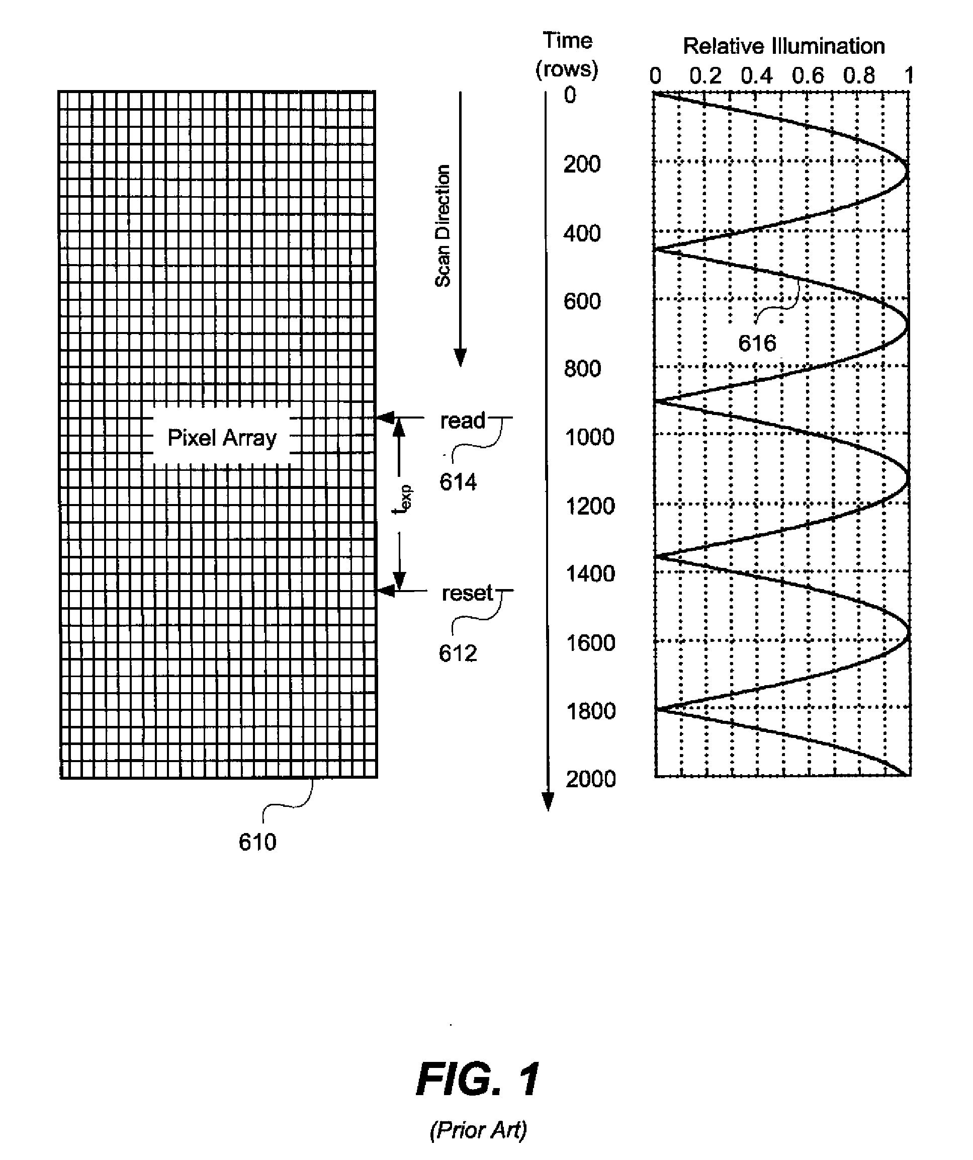
FIELD OF THE INVENTION[0001]The present invention relates to image processing using a digital sensor array and more particularly relates to determining when an image capture device operates in an environment having a flickering illuminant.BACKGROUND OF THE INVENTION[0002]Many image capture devices use solid-state image sensors containing a two-dimensional array of pixels. Increasingly, these image sensors are active pixel sensors (APS), also known as CMOS sensors, because they can be fabricated at high resolution using a Complementary Metal Oxide Semiconductor (CMOS) process.[0003]In cameras and other types of image capture devices, CMOS image sensors often control exposure of each pixel by using an electronic rolling shutter, illustrated in the left hand portion of FIG. 1. In this figure, a two-dimensional pixel array 610 is read out a row of pixels at a time, indicated by the arrow labeled scan direction. This read out proceeds row by row with regular timing between the readout of...

Claims


Application Information

Patent Timeline
Patent Type & Authority Applications(United States)
IPC IPC(8): H04N9/73
CPCH04N5/2357H04N5/235H04N23/745H04N23/70
Inventor PILLMAN, BRUCE H.HAMILTON, JR., JOHN F.
Owner INTELLECTUAL VENTURES FUND 83 LLC
Why Eureka
Try Eureka