
Magnetic recording medium and magnetic recording and reproducing device

a recording medium and magnetic technology, applied in the field of magnetic recording medium, can solve the problems of reducing ow, reducing the efficiency of recording and reproducing, and reducing the difficulty of magnetization inversion

Inactive Publication Date: 2010-02-25
SHOWA DENKO KK
View PDF8 Cites 7 Cited by
  • Summary
  • Abstract
  • Description
  • Claims
  • Application Information

AI Technical Summary

Benefits of technology

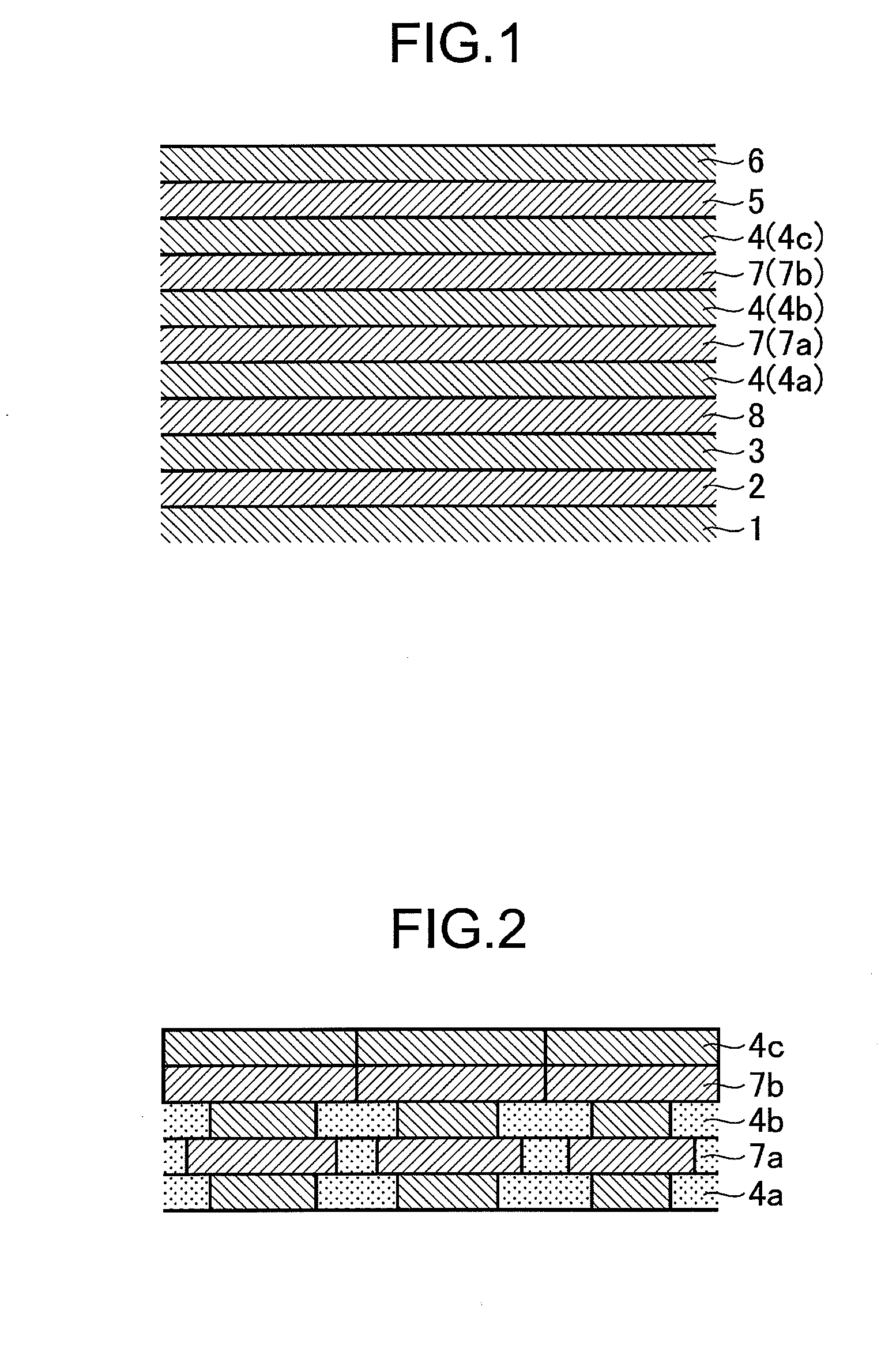
The present invention provides a magnetic recording medium with improved performance. The medium includes a nonmagnetic substrate, a soft magnetic under layer, an orientation adjusting layer, a vertical magnetic layer with an axis of easy magnetization being mainly oriented vertically to the nonmagnetic substrate, and a protective layer. The vertical magnetic layer is composed of three or more layers including a lower layer, an intermediate layer, and an upper layer. The upper layer has a magnetic anisotropic constant (Ku) ranging from 0.8×10⁶ to 4×10⁶ (erg / cc), the intermediate layer has a Ku ranging from 2×10⁶ to 7×10⁶, and the lower layer has a Ku ranging from 1×10⁶ to 4×10⁶. The magnetic layers are bound by ferro-coupling. The magnetic recording medium may also include a nonmagnetic layer between the lower and intermediate magnetic layers or between the intermediate and upper magnetic layers. The magnetic layers may have a granular structure or a nonmagnetic layer with a granular structure. The product of the saturation magnetization and film thickness of the intermediate layer is larger than the product of each magnetic layer. The magnetic recording medium is suitable for recording and reproducing information using a magnetic head.

Problems solved by technology

However, when a magnetic recording medium simply provided with a backing layer as mentioned above is used, it can be unsatisfied in recording and reproducing characteristics, heat fluctuation resistance and recording resolution during the course of recording and reproduction and a magnetic recording medium superior in these characteristics is desired.
However, these two items are contrary to each other and specifically, if one of these items is improved, the other is deteriorated, giving rise to an important problem concerning a high level of compatibility between these characteristics.
However, there is the problem that magnetization inversion is made difficult, and a reduction in OW and an increase in the width of magnetization inversion become a hindrance to the high recording densification of a magnetic recording medium in the future.
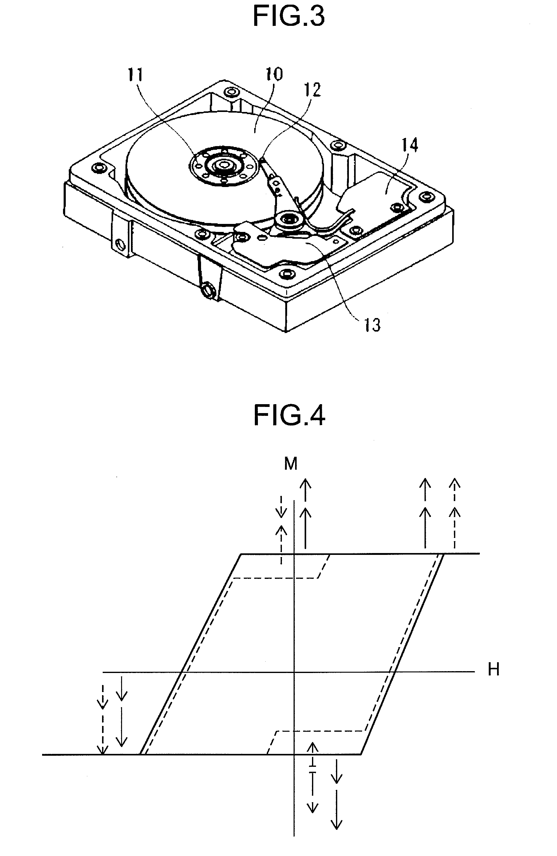
Also, the inventors of the present invention have found that when no nonmagnetic layer exist between each magnetic layer of a laminate structure of the magnetic layer, the multilayered magnetic layers are not reversed simultaneously but gradually reversed, leading to a deterioration in OW and wide magnetization inverse distribution of the magnetic layer, which is a cause of the turbulence of bit boundaries, resulting in an increase in noise.

Method used


Image

  • Magnetic recording medium and magnetic recording and reproducing device
  • Magnetic recording medium and magnetic recording and reproducing device
  • Magnetic recording medium and magnetic recording and reproducing device

Examples


example 1

[0154]A washed glass substrate (manufactured by Konica Minolta Co., Ltd., outside diameter: 2.5 inch) was put in a film-forming chamber of a DC magnetron sputtering apparatus (trade name: C-3040, manufactured by Anerva Corporation) and the film-forming chamber was evacuated until the ultimate degree of vacuum reached 1×10⁻¹⁵ Pa. Then, an adhesion layer having a thickness of 10 nm was formed on this glass substrate by using a Cr target. Using a target of Co-20Fe-5Zr-5Ta {content of Fe: 20 at %, content of Zr: 5 at % and content of Ta: 5 at %, balanced with Co}, a soft magnetic layer having a thickness of 25 nm was formed at a substrate temperature of 100° C. or less. A Ru layer was formed on the soft magnetic layer in a thickness of 0.7 nm and then, a soft magnetic layer of Co-20Fe-5Zr-5Ta was formed in a thickness of 25 nm as a soft magnetic under layer 2. The product Bs·t (T·nm) of the saturated magnetic flux density Bs (T) and film thickness t (nm) of this layer was confirmed to b...

example 1-2 , example 1-3

Example 1-2, Example 1-3, Comparative Example 1

[0167]A vertical magnetic recording medium was produced in Example 1-2 in the same manner as in Example 1 except for the nonmagnetic layer 7a was not formed, a vertical magnetic recording medium was produced in Example 1-3 in the same manner as in Example 1 except for the nonmagnetic layer 7b was not formed and a vertical magnetic recording medium was produced in Comparative Example 1 in the same manner as in Example 1 except for the nonmagnetic layers 7a and 7b were not formed. The results are shown in Table 1.

[0168]As shown in Table 1, it was found that Example 1 had a higher S / N ratio and higher OW characteristics required for high-density recording as compared with Examples 1-2, 1-3 and Comparative Example 1 in which the nonmagnetic layer 7a or 7b (or both) was not formed.

examples 2 to 37

[0170]Vertical magnetic recording mediums were obtained in the same manner as in Example 1 except that the material and film thickness of each of the magnetic layers 4a, 4b and 4c were changed. The results are shown in Tables 2 to 4.

TABLE 2Soft magnetic under layerOrientation adjusting layerMagnetic layer 4aCompositionBs * tCompositionThicknessCompositionThicknessComposition(mol %)(T · nm)(mol %)(nm)(mol %)(nm)(mol %)Example 1Co20Fe5Zr5Ta65Ni6W5Ru2091(Co15Cr16Pt)—6SiO2—3TiO2Example 2Co20Fe5Zr5Ta65Ni6W5Ru2091(Co11Cr16Pt)—6SiO2—3TiO2Example 3Co20Fe5Zr5Ta65Ni6W5Ru2091(Co18Cr16Pt)—6SiO2—3TiO2Example 4Co20Fe5Zr5Ta65Ni6W5Ru2089(Co15Cr16Pt)—7SiO2—4TiO2Example 5Co20Fe5Zr5Ta65Ni6W5Ru2092(Co15Cr16Pt)—5SiO2—3Cr2O3Example 6Co20Fe5Zr5Ta65Ni6W5Ru2090(Co15Cr16Pt)—3TiO2—3SiO2—3Cr2O3Example 7Co20Fe5Zr5Ta65Ni6W5Ru2094(Co15Cr16Pt)—3Ta2O5—3TiO2Example 8Co20Fe5Zr5Ta65Ni6W5Ru2091(Co12Cr16Pt4B)—6SiO2—3TiO2Example 9Co20Fe5Zr5Ta65Ni6W5Ru2091(Co10Cr16Pt7Ru)—6SiO2—3TiO2ExampleCo20Fe5Zr5Ta65Ni6W5Ru2091(Co10Cr1...


PUM

PropertyMeasurementUnit
surface roughnessaaaaaaaaaa
flying heightaaaaaaaaaa

Abstract

The invention relates to a magnetic recording medium comprises a nonmagnetic substrate on which at least a soft magnetic under layer, an orientation adjusting layer that controls the orientation of a layer just thereon, a vertical magnetic layer with an axis of easy magnetization being mainly oriented vertically to the nonmagnetic substrate and a protective layer are disposed, the vertical magnetic layer is constituted of three or more layers including a lower layer, an intermediate layer and an upper layer from the substrate side, wherein the lower, intermediate and upper magnetic layers are constituted of magnetic particles which are columnar crystals extending continuously from the lower layer to the upper layer, the magnetic recording medium further comprises a nonmagnetic layer between the lower and intermediate magnetic layers or between the intermediate and upper magnetic layers, wherein the upper layer has a magnetic anisotropic constant (Ku) ranging from 0.8×10⁶ to 4×10⁶ (erg / cc), the intermediate layer has a magnetic anisotropic constant (Ku) ranging from 2×10⁶ to 7×10⁶ (erg / cc) and the lower layer has a magnetic anisotropic constant (Ku) ranging from 1×10⁶ to 4×10⁶ (erg / cc), and the lower, intermediate and upper magnetic layers are bound by ferro-coupling.

Description

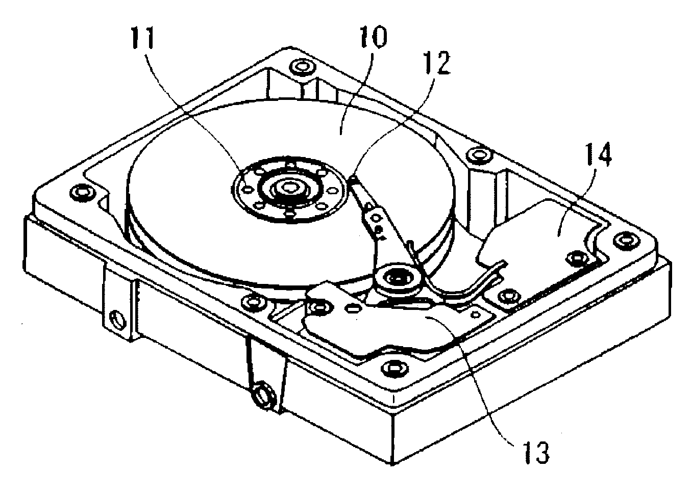
BACKGROUND OF THE INVENTION[0001]1. Field of the Invention[0002]The present invention relates to a magnetic recording medium provided with a nonmagnetic substrate on which at least an orientation adjusting layer that controls the orientation of a layer just above the nonmagnetic substrate, a vertical magnetic layer with an axis of easy magnetization primarily oriented vertically to the nonmagnetic substrate and a protective layer are disposed, and to a magnetic recording and reproducing device.[0003]2. Description of the Prior Art[0004]A hard disk drive (HDD) that is a type of magnetic recording and reproducing device is currently increased in recording density at a rate of 50% or more a year and it is said that this trend will be continued after this. This is the reason why the development of a magnetic recording head suitable for high-density recording and the development of a magnetic recording medium are now in progress.[0005]At present, the magnetic recording medium mounted on ...

Claims


Application Information

Patent Timeline
Patent Type & Authority Applications(United States)
IPC IPC(8): G11B5/127G11B5/72
CPCG11B5/66G11B5/65G11B5/678
Inventor SHIMIZU, KENJIKISHIMOTO, JUNICHI
Owner SHOWA DENKO KK
Learn More