


Quick Research
Generate reliable direction feasibility study reports for your R&D in just a few steps.

Technical Q&A
Discover and master advanced knowledge NOW. Basics, ideas, possibilities, all at once.

Find Solutions
As an expert in R&D theories, this can generate solutions to your technical problems instantly.

Evaluate Feasibility
Analyze your overall solution with one click, know your potential R&D risks in advance.

Monitor Landscape
Get weekly tech updates, stay abreast of the latest tech innovations and key insights.
Medical Instrument Insertion Guide System
- Summary
- Abstract
- Description
- Claims
- Application Information
AI Technical Summary
Benefits of technology
Problems solved by technology
Method used
Image

Examples
first embodiment
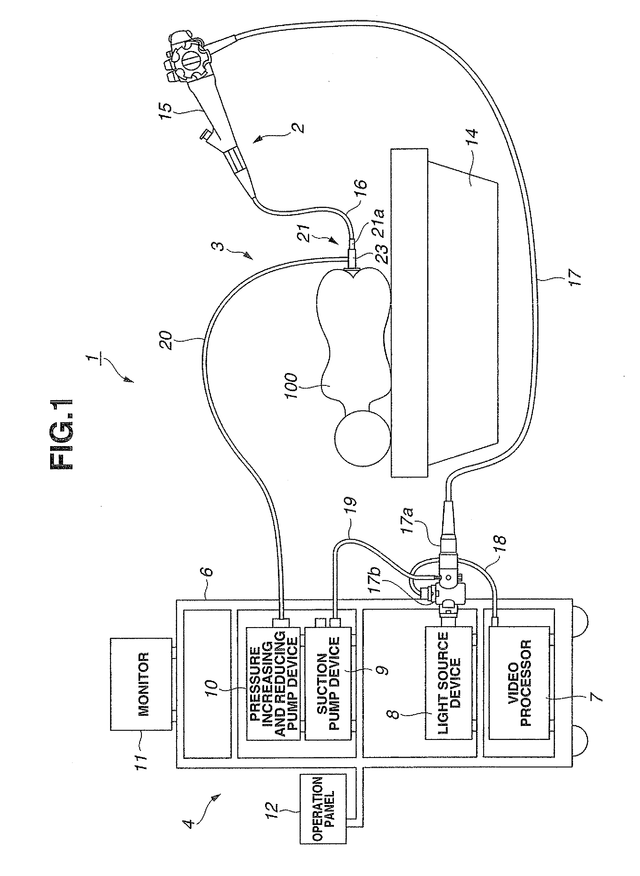
[0060]FIGS. 1 to 24 show a first embodiment of the present invention. FIG. 1 shows an entire configuration of an endoscope system. In the present embodiment, a case of performing a large intestine endoscopy using an endoscope system will be exemplified and described. In FIG. 1, an endoscope system 1 includes an endoscope 2 as an example of a medical instrument, an insertion guide system 3 as an example of a medical instrument insertion guide system, and external devices 4 connected to the endoscope 2 and the insertion guide system 3.
[0061]The external devices 4 are collectively placed in a trolley 6. In the trolley 6, a video processor 7, a light source device 8, a suction pump device 9, and a pressure increasing and reducing pump device 10 as the external devices are placed in order from a bottom side. A monitor 11 that displays an endoscope image or the like is placed on a top surface of the trolley 6, and an operation panel 12 such as a touch panel or a keyboard is provided on on...
second embodiment
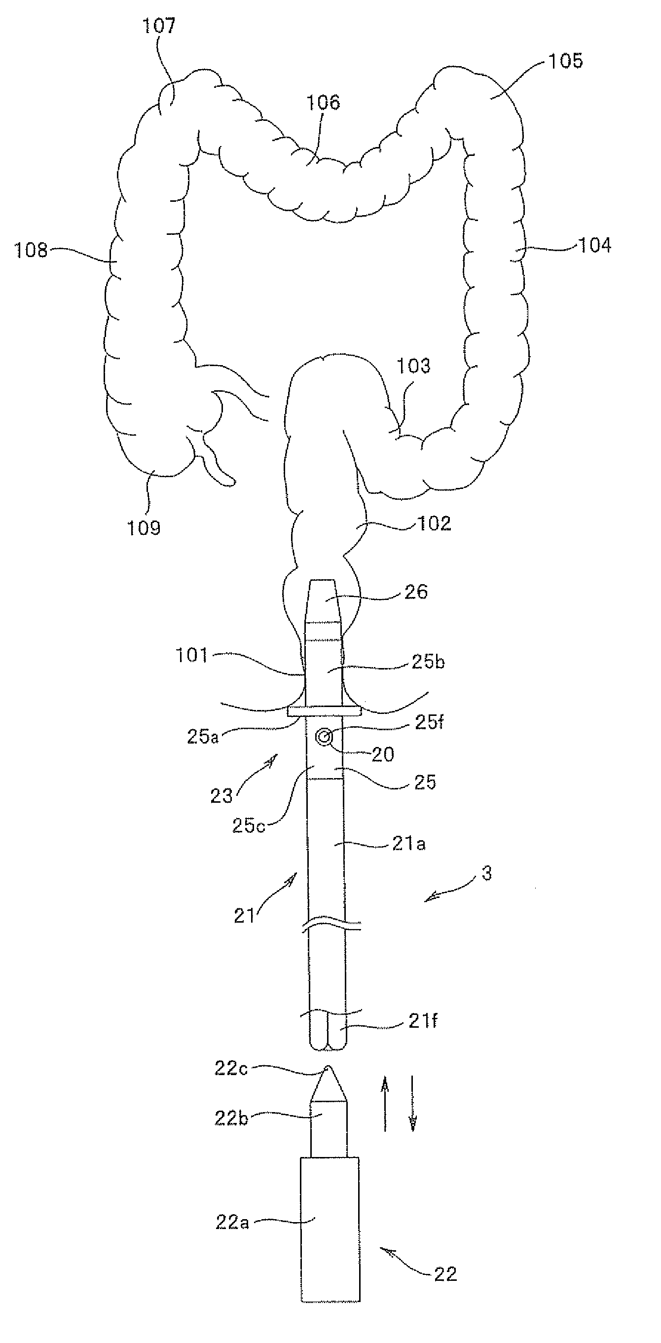
[0103]FIGS. 25 and 26 show a second embodiment of the present invention. FIG. 25 is a half-sectional side view of a guide sheath, and FIG. 26 is a side view of a guide sheath unit 21. The same components as in the first embodiment are denoted by the same reference numerals and descriptions thereof will be omitted.
[0104]In the present embodiment, the guide sheath 21a described in the first embodiment includes indexes indicating an insertion length.
[0105]Specifically, the guide sheath 21a is secured to the inner periphery of the sheath support member 23, and as shown in FIG. 26, when the rear end is pressed by the distal end insertion portion 22c of the pressing member 22 (see FIG. 11), the outer surface 21c of the rear end is turned inward and the inner surface 21b of the distal end surface is turned outward, and thus the distal end surface is advanced. In the present embodiment, indexes 31 (scales in the drawings) are indicated at predetermined intervals on the inner surface 21b and...
third embodiment
[0107]FIG. 27 is a side view of a guide sheath unit according to a third embodiment of the present invention. The present embodiment is a variant of the second embodiment. In the second embodiment, the indexes 31 indicating the insertion length of the guide sheath 21a are set with reference to the distal end surface of the guide cap 26 provided in the sheath support member 23, but in the present embodiment, the insertion length of the guide sheath 21a can be grasped at a hand side of the operator.
[0108]Specifically, as shown in FIG. 27, in an initial state where the distal end of the guide sheath 21a is in alignment with the distal end of the guide cap 26, the rear end of the guide sheath 21a at a hand side of the operator (a right side in FIG. 27) indicates 0 [cm], and an index 31 (170 [cm] in FIG. 27) indicating a maximum insertion length of the guide sheath 21a is provided on the rear end of the grip portion 25c of the main body 25 in the sheath support member 23.
[0109]Thus, the ...
PUM
 Abstract
Description
Claims
Application Information
 - R&D Engineer
- R&D Manager
- IP Professional
- Industry Leading Data Capabilities
- Powerful AI technology
- Patent DNA Extraction
Browse by: Latest US Patents, China's latest patents, Technical Efficacy Thesaurus, Application Domain, Technology Topic, Popular Technical Reports.
© 2024 PatSnap. All rights reserved.Legal|Privacy policy|Modern Slavery Act Transparency Statement|Sitemap|About US| Contact US: help@patsnap.com