Parking assist system

a technology of assist system and parking target, which is applied in the direction of steering initiation, vessel parts, instruments, etc., can solve the problems of prolonging the time required, affecting the safety of drivers, and not necessarily appropriate positioning, so as to reduce the difficulty of drivers

Active Publication Date: 2010-02-25
AISIN SEIKI KK
View PDF6 Cites 86 Cited by
  • Summary
  • Abstract
  • Description
  • Claims
  • Application Information

AI Technical Summary

Benefits of technology

[0032]If the guidance of reverse movement is effected by automatic steering control, this will even further alleviate the driver's difficulty. As described above, the parking path from the reverse start posi

Problems solved by technology

However, as the stop position used as the reverse start position is at the driver's discretion, the position is not necessarily appropriate.
For instance, if the vehicle was stopped after a more than necessary amount of forward movement and/or steering amount, the period required for the subsequent reverse movement to the parking target position will be longer disadvantageously.
Conversely, i

Method used


Image

  • Parking assist system
  • Parking assist system
  • Parking assist system

Examples


first embodiment

[0052]Next, embodiments of the present invention will be explained with reference to the accompanying drawings.

[0053]In the first embodiment, explanation will be given by way of an example of a parking assist system implementing automatic steering control.

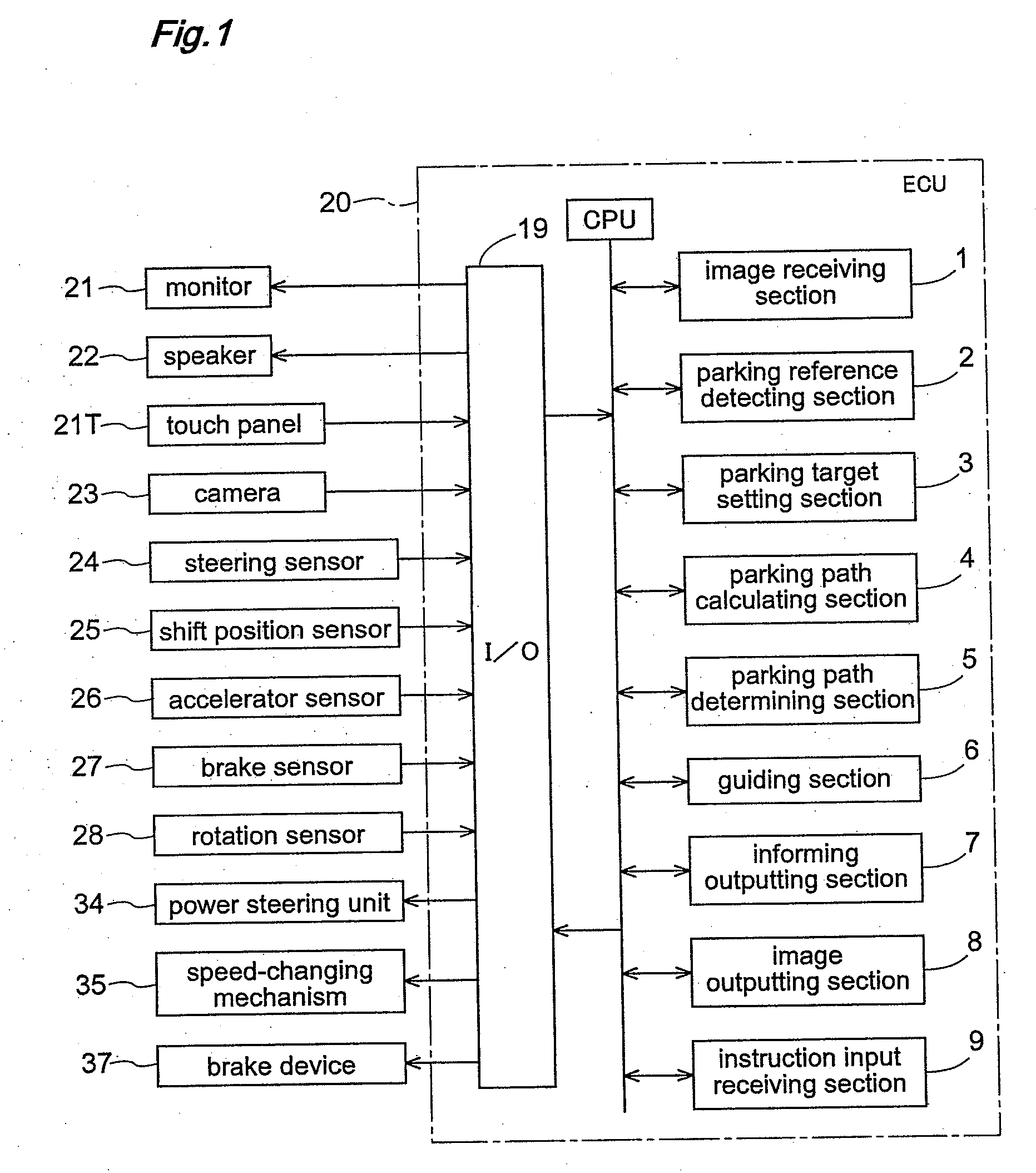
[0054]FIG. 1 is a block diagram schematically showing an example of construction of a parking assist system of the present invention.

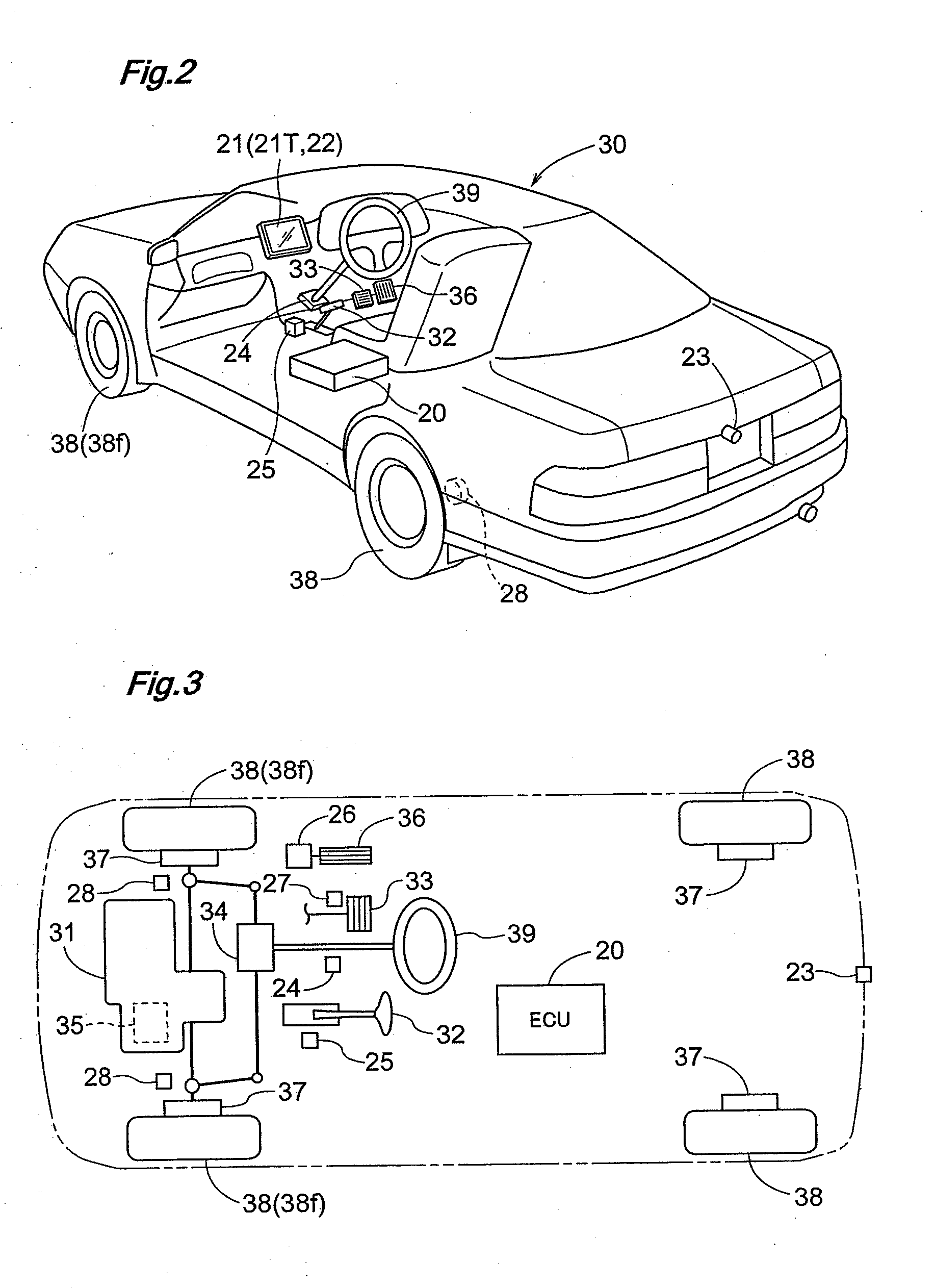
[0055]FIG. 2 is a perspective view showing an example of a vehicle 30 mounting the parking assist system of the invention.

[0056]FIG. 3 is a block diagram schematically showing an example of construction of the vehicle 30.

[0057]The parking assist system of the invention comprises an ECU 20 as the core component thereof. The ECU 20 includes an input / output interface 19 for effecting inputs / outputs of information and includes also a microprocessor and a DSP (digital signal processor) for processing information from this input / output interface. Needless to say, the input / output interface 19 can be partial...

second embodiment

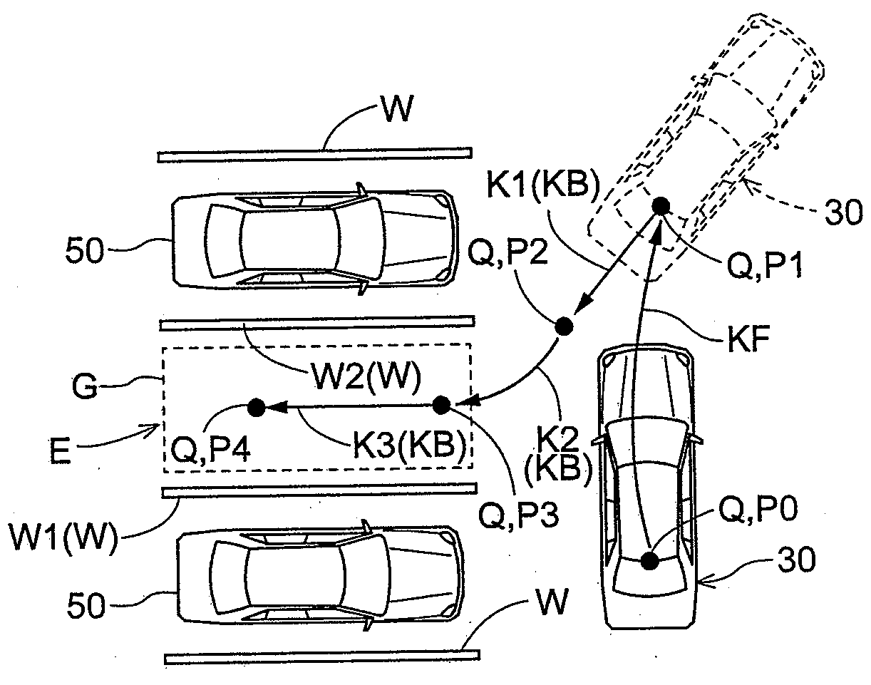
[0145]In the second embodiment, there will be described a case where the reverse movement along the parking path KB is effected by manual maneuvering by the driver. This second embodiment differs from the first embodiment described above in that the reverse guiding step is effected not by automatic steering control, but by manual maneuvering by the driver. In the other respects, the second embodiment does not differ from the first embodiment, therefore, the description thereof will be omitted and only the forward guiding step alone will be explained.

[0146][Reverse Guiding Step (Steering Assisting Step (FIG. 12))]

[0147]In the display screen of the monitor 21 shown in FIG. 17, once the position of the parking target area G (parking target position P4) has been fixedly determined (OK-ed), the guiding section 6 starts reverse guiding. FIG. 18 is an explanatory view showing an example of display screen of the monitor 21 after depression of the OK button. As shown in FIG. 18, by the image...


PUM


Abstract

The parking assist system assists the maneuvering for moving a vehicle to a reverse start position, then moving it in reverse from the reverse start position to a predetermined parking position in a manner as follows. A parking target setting section sets a parking target position corresponding to the predetermined parking position, based upon a parking reference detected based on image data captured from the scene around the vehicle. A parking path calculating section sequentially calculates a parking path from a present position of the vehicle to the parking target position, in the course of forward movement along a forward path. A parking path determining section determines whether an effective parking path has been established or not, based upon result of calculation by the parking path calculating section.

Description

TECHNICAL FIELD[0001]The present invention relates to a parking assist system for assisting a maneuvering operation in which a vehicle is maneuvered forward to a reverse start potion (a shift-lever switching position for the driver to switch the position of the shift lever into reverse) for parking the vehicle during its forward maneuvering, then the vehicle is maneuvered reverse from this reverse start position to be parked at a predetermined parking position.BACKGROUND ART[0002]A parking operation for parking a vehicle generally involves steering and reverse maneuvering in a small space, thus requiring relatively high maneuvering skill. Then, in order to alleviate the trouble for the diver during parking operation, various types of parking assist systems and maneuvering assist systems have been proposed. Patent Document 1 identified below discloses an invention relating to a parking assist system for assisting a maneuvering operation including a forward movement to a reverse start...

Claims


Application Information

Patent Timeline
IPC IPC(8): B60W30/06B60R1/00B60R11/02B60R16/02B60R21/00B60W10/18B60W10/184B60W10/20B60W30/00
CPCB60R1/00B60R2300/304B60R2300/305B60R2300/806B62D15/0285B60W10/20B60W2420/403B62D15/027B60W10/18
Inventor TANAKA, YU
Owner AISIN SEIKI KK
Why Eureka
Try Eureka